


222
Motor brake and stop operation
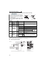
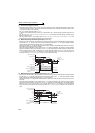
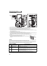
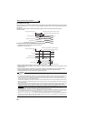
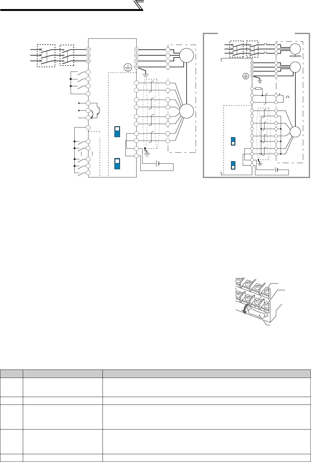
(1) Connection example
*1 The pin number differs according to the encoder used.
*2 Use Pr. 178 to Pr. 189 (input terminal function selection) to assign the function to any of terminal. (Refer to page 231.)
*3 Use Pr. 190 to Pr. 196 (output terminal function selection) to assign the function to any of terminal. (Refer to page 239.)
*4 Connect the encoder so that there is no looseness between the motor and motor shaft. Speed ratio should be 1:1.
*5 Earth (Ground) the shielded cable of the encoder cable to the enclosure with a P clip, etc. (Refer to page 38.)
*6 For the differential line driver, set the terminating resistor selection switch to ON position (initial status) to use. (Refer to page 34.)
Note that the terminating resistor switch should be set to OFF position when sharing the same encoder with other unit (NC, etc) or a terminating
resistor is connected to other unit.
For the complementary, set the switch to OFF position.
*7 For terminal compatibility of the FR-JCBL, FR-V7CBL and FR-A7AP, refer to page 36.
*8 A separate power supply of 5V/12V/15V/24V is necessary according to the encoder power specification. Make the voltage of the external power
supply the same as the encoder output voltage, and connect the external power supply between PG and SD.
When performing encoder feedback control and vector control together, an encoder and power supply can be shared.
*9 When a stop position command is input from outside, a plug-in option FR-A7AX is necessary. Refer to page 223 for external stop position
command.)
*10 For the fan of the 7.5kW or lower dedicated motor, the power supply is single phase. (200V/50Hz, 200 to 230V/60Hz)
*11 Assign OH (external thermal input) signal to the terminal CS. (Set "7" in Pr. 186 )
Connect a 2W1kΩ resistor between the terminal PC and CS(OH).
Install the resistor pushing it against the bottom part of the terminal block so as to avoid a contact with
other cables.
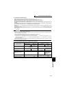
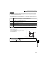
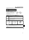
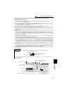
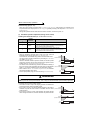
<Setting>
If the orientation command signal (X22) is turned ON during operation after the various
parameters have been set, the speed will decelerate to the "orientation switchover speed". After the "orientation stop
distance" is calculated, the speed will further decelerate, and the "orientation state" (servo lock) will be entered. The
"orientation complete signal" (ORA) will be output when the "orientation complete width" is entered.
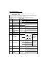
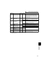
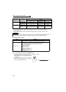
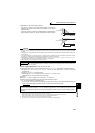
(2) Setting I/O signals
Signal Signal Name Application Explanation
X22*1 Orientation command input
Used to enter an orientation signal for orientation.
For the terminal used for X22 signal input, set "22" in any of Pr. 178 to Pr. 189 to assign
the function.
SD Contact input common Common terminal for the orientation signal.
ORA
*2
Orientation complete signal
output
Switched low if the orientation has stopped within the in-position zone while the start
and orientation signals are input.
For the terminal used for the ORA signal output, assign the function by setting "27
(positive logic) or 127 (negative logic)" in any of Pr. 190 to Pr. 196.
ORM
*2 Orientation fault signal output
Switched low if the orientation has not stopped within the in-position zone while the
start and orientation signals are input.
For the terminal used for the ORM signal output, assign the function by setting "28
(positive logic) or 128 (negative logic)" in any of Pr. 190 to Pr. 196.
SE Open collector output common Common terminal for the ORA and ORM open collector output terminals.
*1 For X22 signals, assign functions to any of terminal using Pr. 178 to Pr. 189 (output terminal function selection). (Refer to page 231)
*2 For ORA and ORM signals, assign functions to any of terminal using Pr. 190 to Pr. 196 (output terminal function selection). (Refer to page 239)
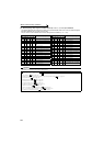
SF-V5RU
U
V
W
U
A
B
C
V
W
E
G1
G2
Earth (Ground)
2W1kΩ
Three-phase
AC power
supply
MCCB MC
IM
FAN
External
thermal relay
input
*11
Thermal
relay
protector
*10
CS(OH)
SD
PC
OCR
Inverter
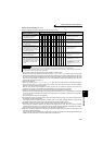
For complementary type (SF-V5RU)
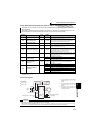
Three-phase
AC power
supply
MCCB
R/L1
S/L2
T/L3
DY
SF-JR motor with encoder
U
V
W
U
V
W
E
C
*5
*1
*4
*9
*6
*7
*1
*4
*6
*7
X0
X1
X14
X15
R
PA1
FR-A7AP
PA2
PB1
PB2
PZ1
PZ2
PG
PG
SD
SD
Differential
Terminating
resistor ON
OFF
Complementary
A
N
B
P
H
K
IM
Differential
Terminating
resistor ON
OFF
Complementary
Forward rotation start
Reverse rotation start
Orientation command
Contact input common
STF
STR
SD
SD
X22*2
Encoder
Earth (Ground)
Inverter
ORM
ORA*3
SE
*3
FR-A7AX
A
*5
B
PA1
FR-A7AP
PA2
PB1
PB2
PZ1
PZ2
PG
PG
SD
SD
C
D
F
G
S
R
Encoder
5VDC power
supply
*8
(+)
(-)
12VDC power
supply
*8
(+)
(-)
MC
CS(OH)
Resistor (2W1kΩ)
PC
Control circuit
terminal block