


43
Connection of stand-alone option units
2
WIRING
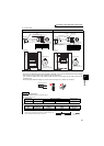
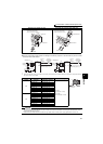
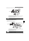
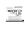
(2) FR-BR-(H) connection example with resistor unit
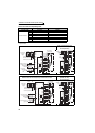
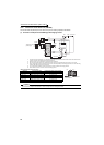
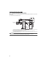
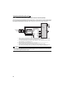
(3) Connection example with MT-BR5 type resistor unit
After making sure that the wiring is correct, set the following parameters:
Pr. 30 Regenerative function selection = "1"
Pr. 70 Special regenerative brake duty = "0 (initial value)"
Set Pr. 0 Brake mode selection = "2" in the brake unit FR-BU2.
*1 Connect the inverter terminals (P/+, N/-) and brake unit (FR-BU2) terminals so that their terminal names match with each other.
(Incorrect connection will damage the inverter and brake unit.)
*2 When the power supply is 400V class, install a step-down transformer.
*3 Be sure to remove the jumper across terminals PR and PX when using the FR-BU with the inverter of 7.5K or lower.
*4 The wiring distance between the inverter, brake unit (FR-BU) and resistor unit (FR-BR) should be within 5m. Even when the
wiring is twisted, the cable length must not exceed 10m.
*5 The contact between TH1 and TH2 is closed in the normal status and is open at a fault.
CAUTION
⋅ Do not remove a jumper across terminal P/+ and P1 except when connecting a DC reactor.
*1 Connect the inverter terminals (P/+, N/-) and brake unit (FR-BU2) terminals so that their terminal names match with each other.
(Incorrect connection will damage the inverter and brake unit.)
*2 When the power supply is 400V class, install a step-down transformer.
*3 The wiring distance between the inverter, brake unit (FR-BU2) and resistor unit (MT-BR5) should be within 5m. If twisted wires
are used, the distance should be within 10m.
*4 The contact between TH1 and TH2 is open in the normal status and is closed at a fault.
*5 CN8 connector used with the MT-BU5 type brake unit is not used.
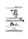
CAUTION
⋅ The stall prevention (overvoltage), oL, does not occur while Pr.30 Regenerative function selection = "1" and Pr.70 Special
regenerative brake duty = "0% (initial value)." (Refer to page 207 for details.)
U
V
W
P/+
N/-
R/L1
S/L2
T/L3
Motor
IM
Inverter
PR
N/-
BUE
SD
P/+
P
A
B
C
FR-BU2
FR-BR
TH2
TH1
PR
Three phase AC
power supply
MCCB
MC
MC
OFFON
MC
T
PR
PX
*1
*1
*5
5m or less
*4
*4
*3
*2
MC
R/L1
Motor
IM
Inverter
S/L2
T/L3
U
V
P/+
N/-
P
PR
5m or less
W
Three phase AC
power supply
MCCB
TH1
TH2
MC
CR1
OFFON
MC
CR1
T
*3
*1
*1
*3
*5
*4
P
N
BUE
SD
P
PR
Brake unit
FR-BU2
Resistor unit
MT-BR5
*2