


218
Motor brake and stop operation
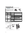
(1) Set the brake sequence mode
⋅ Select either Real sensorless vector control, vector control (speed control) or Advanced magnetic flux vector control.
The brake sequence function is valid only when the External operation mode, External/PU combined operation mode
1 or Network operation mode is selected.
⋅
Set "7 or 8" (brake sequence mode) in Pr. 292 .
To ensure more complete sequence control, it is recommended to set "7" (brake opening completion signal input) in
Pr. 292 .
⋅ Set "15" in any of Pr. 178 to Pr. 189 (input terminal function selection) and assign the brake opening completion signal
(BRI) to the input terminal.
⋅ Set "20 (positive logic)" or "120 (negative logic)" in any of Pr. 190 to Pr. 196 (output terminal function selection) and
assign the brake opening request signal (BOF) to the output terminal.
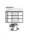
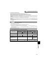
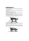
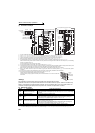
(2) With brake opening completion signal input
(Pr. 292
= "7")
⋅ When the start signal is input to the inverter, the inverter starts running. When the internal speed command reaches
the value set in Pr. 278 and the output current is not less than the value set in Pr. 279 , the inverter outputs the brake
opening request signal (BOF) after the time set in Pr. 280 has elapsed.
When the time set in Pr. 281 elapses after the brake opening completion signal (BRI) was activated, the inverter
increases the output frequency to the set speed.
⋅ When the inverter decelerates to the frequency set in Pr.282 during deceleration, the inverter turns OFF the BOF
signal and decelerates further to the frequency set in Pr.278. After electromagnetic brake operation completes and
inverter recognizes the turn OFF of BRI signal, the inverter holds the frequency set in Pr.278 for the time set in
Pr.283. And after the time set in Pr.283 passes, the inverter decelerates again. The inverter finally stops when its
frequency reaches to Pr.13 Starting frequency setting or 0.5Hz, whichever is lower.
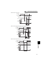
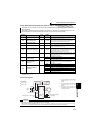
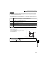
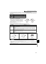
(3) Without brake opening completion signal input
(Pr. 292
= "8")
⋅
When the start signal is input to the inverter, the inverter starts running. When the internal speed command reaches
the value set in Pr. 278 and the output current is not less than the value set in Pr. 279 , the inverter outputs the brake
opening request signal (BOF) after the time set in Pr. 280 has elapsed.
When the time set in Pr. 281 elapses after the BOF signal is output, the inverter increases the output frequency to the
set speed.
⋅ When the inverter decelerates to the frequency set in Pr.282 during deceleration, the inverter turns OFF the BOF
signal and decelerates further to the frequency set in Pr.278. After the turn OFF of BOF signal, the inverter holds the
frequency set in Pr.278 for the time set in Pr.283. And after the time set in Pr.283 passes, the inverter decelerates
again. The inverter finally stops when its frequency reaches to Pr.13 Starting frequency setting or 0.5Hz, whichever is
lower.
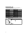
STF
ON
Output current
Brake opening request
(BOF signal)
ON
Electromagnetic brake
operation
Opened
Closed
Closed
Time
Brake opening completion
(BRI signal)
ON
Pr.278
Pr.282
Target frequency
Pr.13
Pr.280
Pr.281
Output frequency(Hz)
Pr.283
Pr.279
Pr.13 setting
or 0.5Hz,
whichever is lowe
r
STF
ON
ON
Pr.278
Pr.282
Target frequency
(Hz)
Pr.281
Pr.283
Pr.280
Pr.279
Pr.13
Output frequency
Brake opening request
(BOF signal)
Electromagnetic brake
operation
Closed
Opened
Closed
Time
Pr.13 setting
or 0.5Hz,
whichever is lowe
r
Output current