


333
Communication operation and setting
4
PARAMETERS
4.24.3 Initial settings and specifications of RS-485 communication
(Pr. 117 to Pr. 124, Pr. 331 to Pr. 337, Pr. 341, Pr. 549)
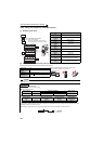
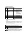
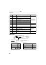
[PU connector communication related parameter]
Use the following parameters to perform required settings for communication between the inverter and personal
computer.
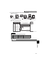
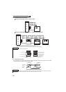
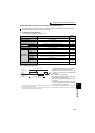
There are two different communications: communication using the PU connector of the inverter and
communication using the RS-485 terminals.
You can perform parameter setting, monitor, etc. from the PU connector or RS-485 terminals of the inverter
using the Mitsubishi inverter protocol (computer link communication).
To make communication between the personal computer and inverter, initialization of the communication
specifications must be made to the inverter.
Data communication cannot be made if the initial settings are not made or there is any setting error.
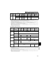
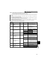
Parameter
Number
Name
Initial Value Setting Range Description
117
PU communication station
number
0 0 to 31
Specify the inverter station number.
Set the inverter station numbers when two or
more inverters are connected to one
personal computer.
118 PU communication speed 192 48, 96, 192, 384
Set the communication speed.
The setting value × 100 equals the
communication speed.
For example, the communication speed is
19200bps when the setting value is "192".
119
PU communication stop bit
length
1
Stop bit length Data length
01 bit
8 bits
1 2 bits
10 1 bit
7 bits
11 2 bits
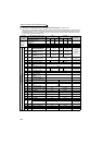
120
PU communication parity
check
2
0 Without parity check
1 With odd parity check
2 With even parity check
121
Number of PU
communication retries
1
0 to 10
Set the permissible number of retries at
occurrence of a data receive error. If the
number of consecutive errors exceeds the
permissible value, the inverter trips.
9999
If a communication error occurs, the inverter
will not trip.
122
PU communication check
time interval
9999
0 No PU connector communication
0.1 to 999.8s
Set the interval of communication check
(signal loss detection) time.
If a no-communication state persists for
longer than the permissible time, the inverter
trips.
9999
No communication check (signal loss
detection)
123
PU communication waiting
time setting
9999
0 to 150ms
Set the waiting time between data
transmission to the inverter and response.
9999 Set with communication data.
124
PU communication CR/LF
selection
1
0 Without CR/LF
1With CR
2 With CR/LF