


436
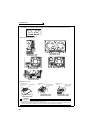
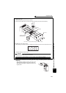
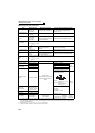
Measurement of main circuit voltages,
currents and powers
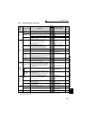
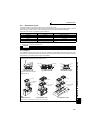
Measuring points and instruments
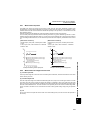
*1 Use an FFT to measure the output voltage accurately. A tester or general measuring instrument cannot measure accurately.
*2 When the carrier frequency exceeds 5kHz, do not use this instrument since using it may increase eddy-current losses produced in metal parts
inside the instrument, leading to burnout. If the wiring length between the inverter and motor is long, the instrument and CT may generate heat
due to line-to-line leakage current.
*3 When the setting of Pr. 195 ABC1 terminal function selection is positive logic
*4 A digital power meter (designed for inverter) can also be used to measure.
Item Measuring Point Measuring Instrument Remarks (Reference Measured Value)
Power supply voltage
V
1
Across R/L1 and S/L2,
S/L2 and T/L3,
T/L3 and R/L1
Moving-iron type AC voltmeter
*4
Commercial power supply
Within permissible AC voltage fluctuation
(Refer to page 444)
Power supply side
current
I
1
R/L1, S/L2, and T/L3
line currents
Moving-iron type AC ammeter
*4
Power supply side
power
P
1
R/L1, S/L2, T/L3 and
R/L1 and S/L2,
S/L2 and T/L3,
T/L3 and R/L1
Digital power meter (designed for
inverter) or electrodynamic type
single-phase wattmeter
P1=W11+W12+W13 (3-wattmeter method)
Power supply side
power factor
Pf
1
Calculate after measuring power supply voltage, power supply side current and power supply side power.
Output side voltage
V
2
Across U and V,
V and W,
W and U
Rectifier type AC voltage meter *1*4
(Moving-iron type cannot
measure)
Difference between the phases is within ±1% of
the maximum output voltage.
Output side current
I
2
U, V and W line
currents
Moving-iron type AC ammeter *2*4
Difference between the phases is 10% or lower
of the rated inverter current.
Output side power
P
2
U, V, W and
U and V,
V and W
Digital power meter (designed for
inverter) or electrodynamic type
single-phase wattmeter
P
2 = W21 + W22
2-wattmeter method (or 3-wattmeter method)
Output side power
factor
Pf
2
Calculate in similar manner to power supply side power factor.
Converter output Across P/+ and N/− Moving-coil type (such as tester)
Inverter LED display is lit. 1.35
× V1
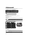
Frequency setting
signal
Across 2, 4(+) and 5
Moving-coil type
(Tester and such may be used)
(Internal resistance: 50kΩ or
larger)
0 to 10VDC, 4 to 20mA
"5" is
common
Across 1(+) and 5 0 to ±5VDC, 0 to ±10VDC
Frequency setting
power supply
Across 10 (+) and 5 5.2VDC
Across 10E(+) and 5 10VDC
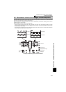
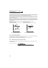
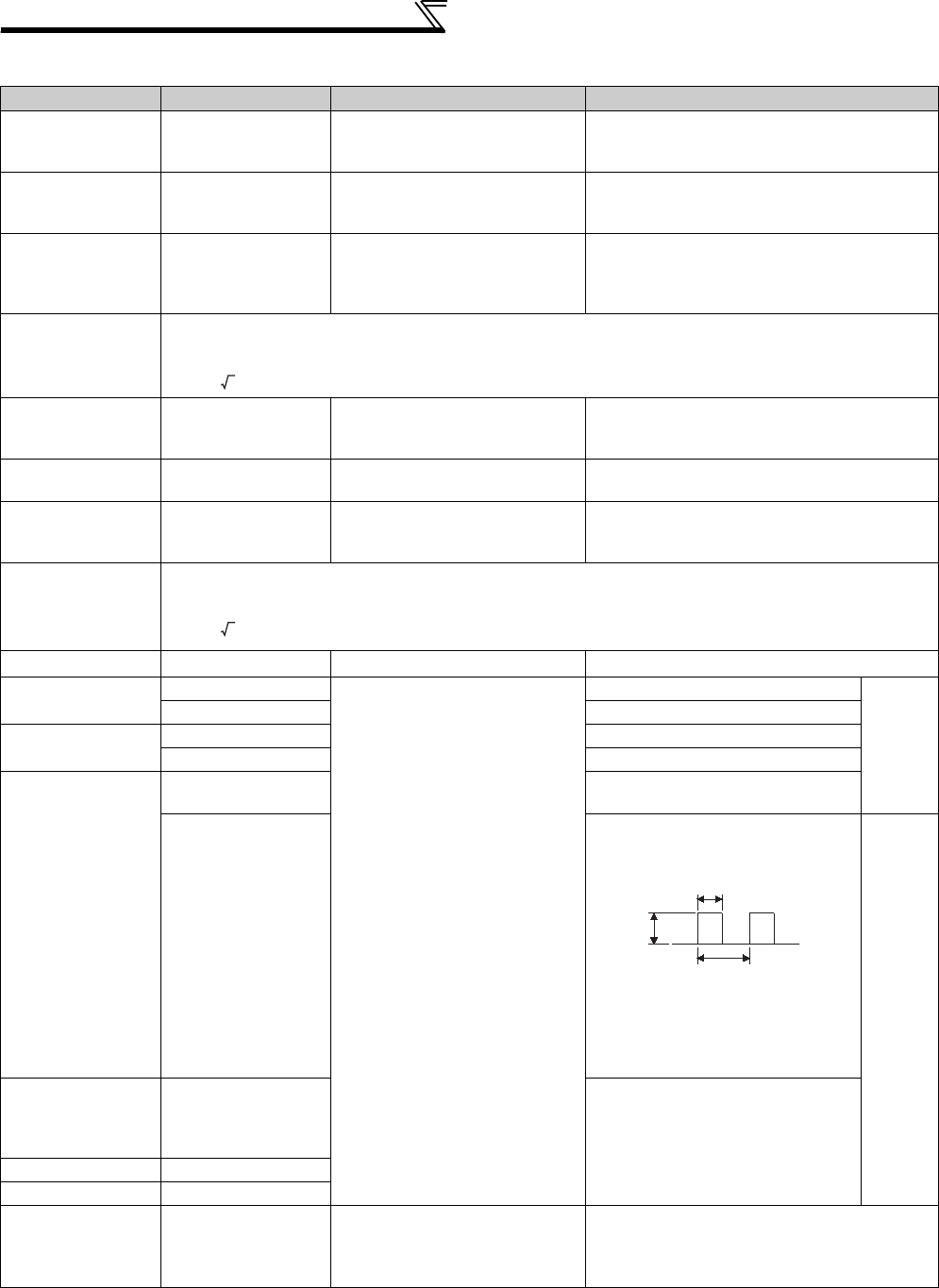
Frequency meter
signal
Across AM(+) and 5
Approximately 10VDC at maximum
frequency (without frequency meter)
Across FM(+) and SD
Approximately 5VDC at maximum
frequency
(without frequency meter)
Pulse width T1:
Adjusted by C0 (Pr. 900)
Pulse cycle T2: Set by Pr. 55
(Valid for frequency
monitoring only)
"SD" is
common
Start signal
Select signal
Across SD and the
following: STF, STR,
RH, RM, RL, JOG, RT,
AU, STOP, CS (+)
When open
20 to 30VDC
ON voltage: 1V or less
Reset
Across RES (+) and SD
Output stop
Across MRS (+) and SD
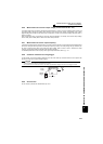
Fault signal
Across A1and C1
Across B1and C1
Moving-coil type
(such as tester)
Conduction check
*3
<Abnormal> <Normal>
Across A1 and C1 No conduction
Conduction
Across B1 and C1
Conduction
No conduction
Pf1 = ————— × 100%
P
1
3 V1 × I1
Pf2 = ————— × 100%
P
2
3 V2 × I2
8VDC
T1
T2