


288
Frequency/torque setting by analog
input (terminal 1, 2, 4)
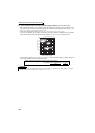
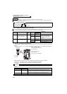
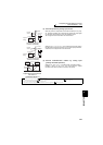
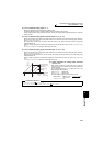
(2) Perform operation by analog input voltage
⋅ The frequency setting signal inputs 0 to 5VDC (or 0 to 10VDC) to across
the terminals 2 and 5. The 5V (10V) input is the maximum output
frequency. The maximum output frequency is reached when 5V (10V) is
input.
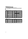
⋅ The power supply 5V (10V) can be input by either using the internal
power supply or preparing an external power supply. The internal power
supply outputs 5VDC across terminals 10 and 5, or 10V across terminals
10E and 5.
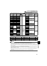
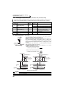
⋅ When inputting 10VDC to the terminal 2, set any of "0, 2, 4, 10, 12, 14"
in Pr. 73. (The initial value is 0 to 5V)
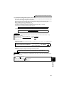
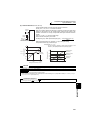
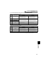
⋅ Setting "1 (0 to 5VDC)" or "2 (0 to 10VDC)" in Pr. 267 and a voltage/
current input switch in the OFF position changes the terminal 4 to the
voltage input specification. When the AU signal turns ON, the terminal 4
input becomes valid.
STF
Inverter
Forward
rotation
Frequency
setting
0 to 5VDC
10
2
5
Connection diagram using
terminal 2 (0 to 5VDC)
Voltage/current
input switch
SD
STF
Inverter
Forward
rotation
Frequency
setting
0 to 10VDC
10E
2
5
Connection diagram
using terminal 2 (0 to 10VDC)
Voltage/current
input switch
SD
STF
AU
DC0 to 5V
10
4
5
Forward
rotation
Frequency
setting
Terminal 4
input selection
Inverter
Voltage/current
input switch
Connection diagram
using terminal 4 (0 to 5VDC)
SD
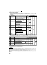
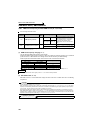
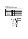
Terminal
Inverter Built-in Power
Supply Voltage
Frequency Setting
Resolution
Pr. 73 (terminal 2
input voltage)
10 5VDC 0.030Hz/60Hz 0 to 5VDC input
10E 10VDC 0.015Hz/60Hz 0 to 10VDC input
REMARKS
The wiring length of the terminal 10, 2, 5 should be 30m maximum.