


229
Motor brake and stop operation
4
PARAMETERS
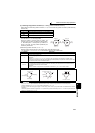
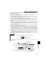
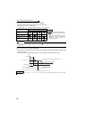
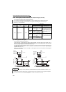
3)Orientation from the reverse rotation direction
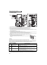
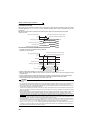
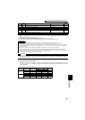
Servo rigidity adjustment (Pr. 362, Pr. 396 to Pr. 398)
•To increase the servo rigidity *1 during orientation stop using Pr. 396 or Pr. 397 , adjust with the following procedures.
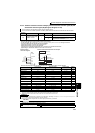
1) Increase the Pr. 362 Orientation position loop gain value to the extent that rocking
*2 does not occur during
orientation stop.
2) Increase Pr. 396 and Pr. 397 at the same rate.
Generally adjust Pr. 396 in the range from 10 to 100, and Pr. 397 from 0.1 to 1.0s.
(Note that these do not need to be set to the same rate.)
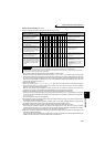
<Example>
When the Pr. 396 value is multiplied by 1.2, divide the Pr. 397 value by 1.2.
If vibration occurs during orientation stop, the scale cannot be raised any higher.
3) Pr. 398 is the lag/advance compensation gain.
The limit cycle
*3 can be prevented by increasing the value, and the running can be stopped stably. However, the
torque in regard to the position deviation will drop, and the motor will stop with deviation.
*1 Servo rigidity: This is the response when a position control loop is configured.
When the servo rigidity is raised, the holding force will increase, the running will stabilize, but vibration will occur easily.
When the servo rigidity is lowered, the holding force will drop, and the setting time will increase.
*2 Rocking: Movement in which return occurs if the stopping position is exceeded.
*3 Limit cycle: This is a phenomenon that generates ± continuous vibration centering on the target position.
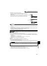
• If the motor is running in the reverse rotation direction, it will make an
orientation stop with the same method as "orientation from the current
rotation direction".
• If the motor is running in forward, it will decelerate, the rotation direction
will be changed to reverse run, and then orientation stop will be executed.
CAUTION
• The encoder should be coupled with the motor shaft oriented with a speed ratio of 1 to 1 without any mechanical looseness.
• To ensure correct positioning, the encoder must be set in the proper rotation direction and the A and B phases connected
correctly.
• Orientation may not be completed if the pulse signals are not received from the encoder during orientation due to a break in the
cable or the like.
• To terminate orientation, the start signal (STF or STR) must be first switched OFF and the orientation signal (X22) must be
switched OFF. As soon as this orientation signal is switched OFF, orientation control ends.
• When performing orientation control, make proper setting of Pr. 350 Stop position command selection and Pr. 360 16-bit data selection.
If the values set are incorrect, proper orientation control will not be performed.
• When orientation control is exercised, PID control is invalid.
REMARKS
If "E.ECT" (no encoder signal) is displayed causing the inverter to trip when the orient signal (X22) is ON, check for a break in the
cable of the Z phase of the encoder.
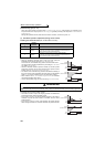
POINT
Application of lag/advance control and PI control
PI control can be applied by setting Pr. 398 to 0. Normally, the lag/advance control is selected. Note that PI control
should be used when using a machine with a high spindle stationary friction torque and requires a stopping position
precision.
Speed
(forward rotation)
X22
ORA
[t]
Speed
(reverse rotation)
X22
ORA
[t]