


217
Motor brake and stop operation
4
PARAMETERS
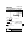
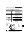
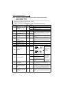
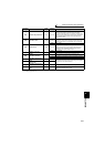
4.14.5 Brake sequence function (Pr. 278 to Pr. 285, Pr. 292)
*1 When exercising vector control with the FR-A7AP/FR-A7AL (option), this parameter changes to excessive speed deviation detection frequency
(For details, refer to page 117)
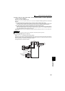
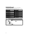
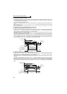
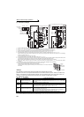
<Connection diagram>
This function is used to output from the inverter the mechanical brake operation timing signal in vertical lift and
other applications.
This function prevents the load from dropping with gravity at a start due to the operation timing error of the
mechanical brake or an overcurrent alarm from occurring at a stop, ensuring secure operation.
Parameter
Number
Name
Initial
Value
Setting
Range
Description
278 Brake opening frequency 3Hz
0 to 30Hz
Set to the rated slip frequency of the motor + about 1.0Hz.
This parameter may be only set if Pr. 278 ≤ Pr. 282.
279 Brake opening current 130%
0 to 220%
Generally, set this parameter to about 50 to 90%. If the setting
is too low, the load is liable to drop due to gravity at start.
Suppose that the rated inverter current is 100%.
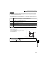
280
Brake opening current
detection time
0.3s 0 to 2s Generally, set this parameter to about 0.1 to 0.3s.
281 Brake operation time at start 0.3s 0 to 5s
Set the mechanical delay time until the brake is loosened.
Set the mechanical delay time until the brake is loosened +
about 0.1 to 0.2s when Pr. 292 = "8".
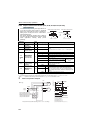
282 Brake operation frequency 6Hz
0 to 30Hz
Set the frequency to activate the mechanical brake by turning
OFF the brake opening request signal (BOF). Generally, set
this parameter to the Pr. 278 setting + 3 to 4Hz.
Setting is enabled only when Pr. 282
≥ Pr. 278.
283 Brake operation time at stop 0.3s 0 to 5s
Set the mechanical delay time until the brake is closed + 0.1s
when Pr. 292=7.
Set the mechanical delay time until the brake is closed + 0.2
to 0.3s when Pr. 292 = 8.
284
Deceleration detection
function selection
0
0 Deceleration is not detected.
1
If deceleration is not normal during deceleration operation,
the inverter fault is provided.
285
Overspeed detection
frequency
*1
9999
0 to 30Hz
If (detected frequency) - (output frequency) ≥ Pr. 285 during
encoder feedback control, the inverter fault (E.MB1) is
provided.
9999 Overspeed is not detected.
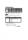
292
Automatic acceleration/
deceleration
0
0 Normal operation mode
1, 11 Shortest acceleration/deceleration mode (Refer to page 180)
3 Optimum acceleration/deceleration mode (Refer to page 181)
5, 6 Elevator mode 1, 2 (Refer to page 163)
7 Brake sequence mode 1
8 Brake sequence mode 2
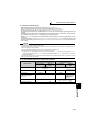
CAUTION
⋅ When brake sequence mode is selected, automatic restart after instantaneous power failure is invalid.
⋅ When using this function, set the acceleration time to 1s or longer.
⋅ Changing the terminal assignment using Pr. 178 to Pr. 189 (input terminal function selection) or Pr. 190 to Pr. 196 (output terminal
function selection) may affect the other functions. Set parameters after confirming the function of each terminal.
Magnetic flux
Magnetic flux
Magnetic flux
Sensorless
Sensorless
Sensorless
Vector
Vector
Vector
Mechanical
brake
R/L1
S/L2
T/L3
Motor
MC
STF
RH
AU(BRI) *
1
SD
MC
24VDC
Brake opening request
signal (BOF)
Start signal
Multi-speed signal
Brake opening completion signal
(BRI)
Sink logic
Pr.184 = 15
Pr.190 = 20
Power
supply
U
V
W
RUN(BOF)
SE
*2
*3
MCCB
*1 The input signal terminal used differs
according to the Pr. 178 to Pr. 189
settings.
*2 The output signal terminal used differs
according to the Pr. 190 to Pr. 19
6
settings.
*3 The current should be within the
permissible current of transistor in the
inverter. (24V 0.1ADC)