


30
Control circuit specifications
2.3.3 Wiring of control circuit
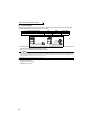
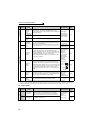
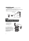
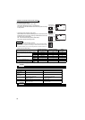
(1) Control circuit terminal layout
(2) Common terminals of the control circuit (SD, 5, SE)
Terminals SD, 5, and SE are all common terminals (0V) for I/O signals and are isolated from each other. Do not earth
(ground) these terminals.
Avoid connecting the terminal SD and 5 and the terminal SE and 5.
Terminal SD is a common terminal for the contact input terminals (STF, STR, STOP, RH, RM, RL, JOG, RT, MRS, RES,
AU, CS) and frequency output signal (FM).
The open collector circuit is isolated from the internal control circuit by photocoupler.
Terminal 5 is a common terminal for frequency setting signal (terminal 2, 1 or 4) and analog output terminal AM.
It should be protected from external noise using a shielded or twisted cable.
Terminal SE is a common terminal for the open collector output terminal (RUN, SU, OL, IPF, FU).
The contact input circuit is isolated from the internal control circuit by photocoupler.
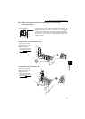
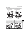
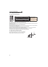
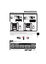
(3) Signal inputs by contactless switches
The contacted input terminals of the inverter (STF, STR, STOP, RH,
RM, RL, JOG, RT, MRS, RES, AU, CS) can be controlled using a
transistor instead of a contacted switch as shown on the right.
External signal input using transistor
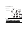
A1 B1 C1 A2
STOP
AURTRHRMRL
OLIPFSU
RUN
B2 C2
10E
10
SD
RES
MRS
STF
SDSDFU PCCS
JOG
STR
254
1
AMFM
SE
Control circuit terminal *
Terminal screw size: M3.5
Tightening torque: 1.2N·m
* Refer to instruction manuals of
options for the available control
terminals other than the standard
control circuit terminal.
+24V
STF, etc
Inverter
SD