


457
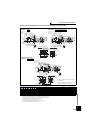
Outline dimension drawings
7
SPECIFICATIONS
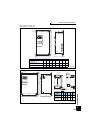
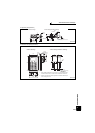
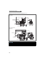
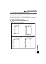
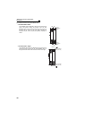
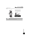
Dedicated motor (SF-V5RU(H)) outline dimension drawings (flange type with brake)
Dimensions table (Unit: mm)
Note)1. Install the motor on the floor and use it with the shaft horizontal.
2.
Leave an enough clearance between the fan suction port and wall to ensure adequate cooling.
Also, check that the ventilation direction of a fan is from the opposite load side to the load side.
3 The size difference of top and bottom of the shaft center height is
4 The 400V class motor has -H at the end of its type name.
5. Since a brake power device is a stand-alone, install it inside the enclosure.
(This device should be arranged at the customer side.)
Frame Number 90L
SF-V5RUF(H)
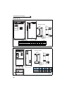
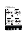
Frame Number 100L, 112M, 132S, 132M
SF-V5RUF(H) , , ,
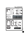
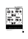
Frame Number 160M, 160L
SF-V5RUF(H) ,
SF-V5RU
F
KB
SF-V5RU
F
K1B
SF-V5RU
F
K3B
SF-V5RU
F
K4B
Flange
Number
Frame
No.
Mass
(kg)
Motor Shaft End
Terminal Screw Size
D KB KD KL KP LA LB LC LE LG LL LN LZ LR Q QK S T U W
U,V,W
A,B,(C)
B1,B2 G1,G2
1 —
— —
FF165 90L 31.5
183.6
198.5
27 220 155 165
130j6
200 3.5 12 442 4 12 50 50 40 24j6 7 4 8 M6 M4 M4 M4
2 1
— —
FF215 100L 50 207 213 27 231 165 215
180j6
250 4 16
481.5
4 14.5 60 60 45 28j6 7 4 8 M6 M4 M4 M4
3 2 1
—
FF215 112M 58 228 239 27 242 178 215
180j6
250 4 16 525 4 14.5 60 60 45 28j6 7 4 8 M6 M4 M4 M4
5 3 2
—
FF265 132S 83 266 256 27 256 197 265
230j6
300 4 20 597 4 14.5 80 80 63
38k6
8 5 10 M6 M4 M4 M4
7 5 3 1 FF265 132M 88 266 294 27 256 197 265
230j6
300 4 20 635 4 14.5 80 80 63
38k6
8 5 10 M6 M4 M4 M4
11 7 5 2 FF300 160M 151 318 318 56 330 231 300
250j6
350 5 20
735.5
4 18.5 110 110 90
42k6
8 5 12 M8 M4 M4 M4
15 11 7 3 FF300 160L 167 318 362 56 330 231 300
250j6
350 5 20
779.5
4 18.5 110 110 90
42k6
8 5 12 M8 M4 M4 M4
1KB 2KB 3KB 5KB 7KB
Connector (for encoder)
MS3102A20-29P
Earth (ground) terminal (M5)
Mark for earthing (grounding)
Suction
Exhaust
Direction of
cooling fan wind
Terminal box for cooling fan
1
2
B
B
Section
AA
LC
LB
LG LE
LL
LR
Q
QK
D
KB
LN LZ
1
2
KD
A
A
LA
KL
φ22
KP
Section BB
U
W
T
S
Main
terminal box
Section BB
W
S
U
T
Connector (for encoder)
MS3102A20-29P
QK
Q
Earth (ground) terminal (M5)
Mark for earthing (grounding)
Suction
Exhaust
Direction of
cooling fan wind
Terminal box for cooling fan
1
2
Section
AA
LC
LB
B
B
LR
LG LE
LL
D
KB
A
LN LZ
A
1
2
LA
KD
KL
φ22
KP
Main
terminal box
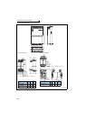
VU
B2B1
W
G1 G2
CBA
For motor (U, V, W)
For cooling fan (A, B)
For brake (B1, B2)
For thermal protector (G1, G2)
Earthing
(grounding)
terminal (M4)
Earthing
(grounding)
terminal (M4)
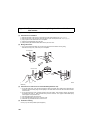
Main terminal box Terminal box for cooling fan
11KB 15KB
Section B
B
W
S
U
T
A
A
LN LZ
2
1
LA
KD
KL
φ22
KP
Connector (for encoder)
MS3102A20-29P
QK
Q
D
Earth (ground) terminal (M8)
Mark for earthing (grounding)
Suction
Direction of
cooling fan wind
Terminal box for cooling fan
1, 2
Section
AA
LC
LB
B
B
LL
KB LR
LG
LE
Exhaust
Main
terminal box
B2B1
U
G2G1
WV
CBA
For cooling fan (A, B, C)
For motor (U, V, W)
Earthing
(grounding)
terminal (M8)
Earthing
(grounding)
terminal (M4)
For brake (B1, B2)
For thermal protector (G1, G2)
Terminal box for cooling fan
Main terminal box
indicates an inserting position of a bolt with hex head holes
for manual opening.
Make sure to earth the earth terminal of the flange section
as well as the earth terminal in the terminal box.
0
-0.5