


31
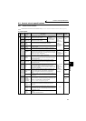
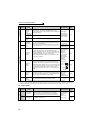
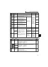
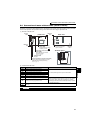
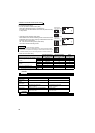
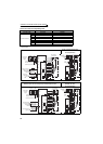
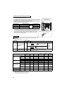
Control circuit specifications
2
WIRING
2.3.4 Wiring instructions
1) It is recommended to use the cables of 0.75mm
2
gauge for
connection to the control circuit terminals.
If the cable gauge used is 1.25mm
2
or more, the front cover may
be lifted when there are many cables running or the cables are
run improperly, resulting in an operation panel contact fault.
2) The wiring length should be 30m (200m for terminal FM)
maximum.
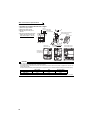
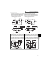
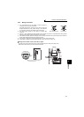
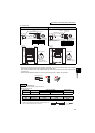
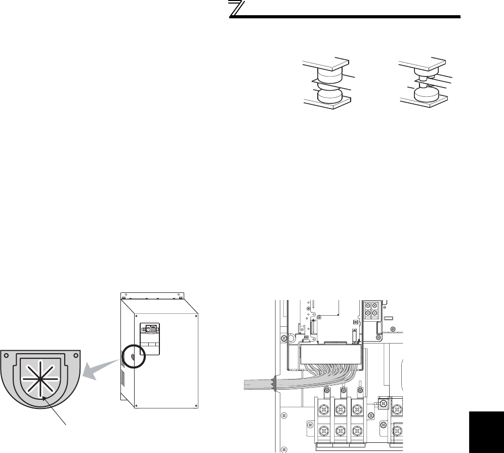
3) Use two or more parallel micro-signal contacts or twin contacts to prevent a contact faults when using contact
inputs since the control circuit input signals are micro-currents.
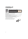
4) Use shielded or twisted cables for connection to the control circuit terminals and run them away from the main and
power circuits (including the 200V relay sequence circuit).
5) Do not apply a voltage to the contact input terminals (e.g. STF) of the control circuit.
6) Always apply a voltage to the fault output terminals (A, B, C) via a relay coil, lamp, etc.
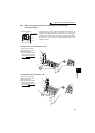
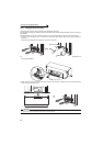
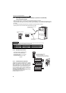
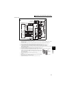
z Wiring of the control circuit of the 75K or higher
For wiring of the control circuit of the 75K or higher, separate away from wiring of the main circuit.
Make cuts in rubber bush of the inverter side and lead wires.
Micro signal contacts Twin contacts
<Wiring>
Rubber bush
(view from the inside)
Make cuts along the lines inside with
a cutter knife and such.