


289
Frequency/torque setting by analog
input (terminal 1, 2, 4)
4
PARAMETERS
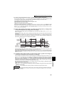
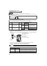
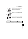
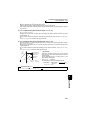
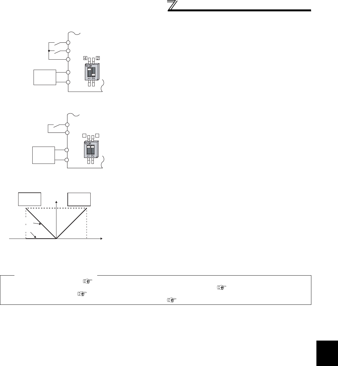
(3) Perform operation by analog input current
⋅ When the pressure or temperature is controlled constant by a fan, pump,
etc., automatic operation can be performed by inputting the output signal
0 to 20mADC of the adjuster to across the terminals 4 and 5.
⋅ The AU signal must be turned ON to use the terminal 4.
⋅ Setting any of "6, 7, 16, 17" in Pr. 73 and a voltage/current input switch in
the ON position changes the terminal 2 to the current input specification.
At this time, the AU signal need not be turned ON.
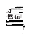
Compensation input characteristic
when STF is on
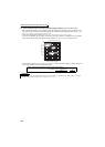
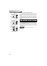
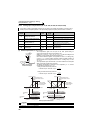
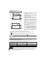
(4) Perform forward/reverse rotation by analog input
(polarity reversible operation)
⋅ Setting any of "10 to 17" in Pr. 73 enables polarity reversible operation.
⋅ Providing ± input (0 to ±5V or 0 to ±10V) to the terminal 1 enables
forward/reverse rotation operation according to the polarity.
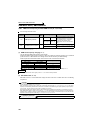
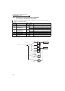
♦ Parameters referred to ♦
Pr. 22 Stall prevention operation level Refer to page 152
Pr. 125 Terminal 2 frequency setting gain frequency, Pr. 126 Terminal 4 frequency setting gain frequency Refer to page 294
Pr. 252, Pr. 253 Override bias/gain Refer to page 290
Pr. 858 Terminal 4 function assignment, Pr. 868 Terminal 1 function assignment Refer to page 285
STF
Inverter
Forward
rotation
Frequency
setting
4
5
AU
Connection diagram using
terminal 4 (4 to 20mADC)
4 to 20mADC
Current
input
equipment
Voltage/current
input switch
SD
STF
2
5
2
4
Forward
rotation
Frequency
setting
Current
input
equipment
Inverter
Voltage/current
input switch
Connection diagram using
terminal 2 (4 to 20mADC)
4 to 20mADC
SD
Forward
rotation
Reverse
rotation
Terminal 1 input (V)
+5
(+10)
-5
(-10)
0
60
Set frequency
(Hz)
Reversible
Not reversible