


416
Causes and corrective actions
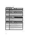
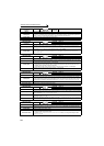
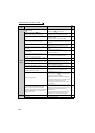
Operation Panel
Indication
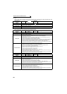
E.P24
FR-PU04
FR-PU07
E.P24
Name
24VDC power output short circuit
Description
When the 24VDC power output from the PC terminal is shorted, this function shuts off the power output.
At this time, all external contact inputs switch OFF. The inverter cannot be reset by entering the RES
signal. To reset it, use the operation panel or switch power OFF, then ON again.
Check point
· Check for a short circuit in the PC terminal output.
Corrective action
· Remedy the earth (ground) fault portion.
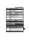
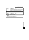
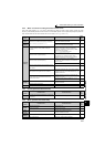
Operation Panel
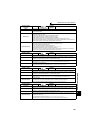
Indication
E.CDO
FR-PU04 Fault 14
FR-PU07 OC detect level
Name
Output current detection value exceeded
Description
Trips the inverter when the output current exceeds the setting of Pr. 150 Output current detection level.
This function is available when Pr. 167 Output current detection operation selection is set to "1". When the
initial value (Pr. 167 = "0") is set, this protective function is not available.
Check point
Check the settings of Pr. 150 Output current detection level, Pr. 151 Output current detection signal delay time,
Pr. 166 Output current detection signal retention time, Pr. 167 Output current detection operation selection.
(Refer to page 248.)
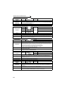
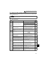
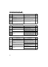
Operation Panel
Indication
E.IOH
FR-PU04 Fault 14
FR-PU07 Inrush overheat
Name
Inrush current limit circuit fault
Description
Stops the inverter output when the resistor of inrush current limit circuit overheated. The inrush current
limit circuit failure
Check point
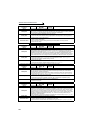
· Check that frequent power ON/OFF is not repeated.
· Check that the primary side fuse (5A) in the power supply circuit of the inrush current limit circuit
contactor (FR-A740-110K or higher) is not fused.
· Check that the power supply circuit of inrush current limit circuit contactor is not damaged.
Corrective action
Configure a circuit where frequent power ON/OFF is not repeated.
If the problem still persists after taking the above measure, please contact your sales representative.
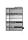
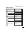
Operation Panel
Indication
E.SER
FR-PU04 Fault 14
FR-PU07 VFD Comm error
Name
Communication fault (inverter)
Description
This function stops the inverter output when communication error occurs consecutively for more than
permissible retry count when a value other than "9999" is set in Pr. 335 RS-485 communication retry count
during RS-485 communication from the RS-485 terminals. This function also stops the inverter output if
communication is broken for the period of time set in Pr. 336 RS-485 communication check time interval.
Check point
Check the RS-485 terminal wiring.
Corrective action
Perform wiring of the RS-485 terminals properly.
Operation Panel
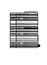
Indication
E.AIE
FR-PU04 Fault 14
FR-PU07 Analog in error
Name
Analog input fault
Description
Stops the inverter output when a 30mA or higher current or a 7.5V or higher voltage is input to terminal
2 while the current input is selected by Pr. 73 Analog input selection, or to terminal 4 while the current
input is selected by Pr. 267 Terminal 4 input selection.
Check point
Check the setting of Pr. 73 Analog input selection, Pr. 267 Terminal 4 input selection and voltage/current
input switch. (Refer to page 286.)
Corrective action
Either give a frequency command by current input or set Pr. 73 Analog input selection, Pr. 267 Terminal 4
input selection, and voltage/current input switch to voltage input.
Operation Panel
Indication
E.USB
FR-PU04 Fault 14
FR-PU07 USB comm error
Name
USB communication fault
Description
When the time set in Pr. 548 USB communication check time interval has broken, this function stops the
inverter output.
Check point Check the USB communication cable.
Corrective action
· Check the Pr. 548 USB communication check time interval setting.
· Check the USB communication cable.
· Increase the Pr. 548 USB communication check time interval setting. Or, change the setting to 9999.
(Refer to page 360)