


138
Position control by vector control
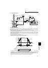
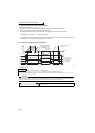
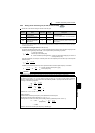
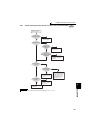
(3) Selection of clear signal (Pr. 429, CLR signal)
⋅ Use this function to zero the droop pulse for home position operation, etc.
⋅ When "0" is set in Pr. 429 , the deviation counter is cleared at the edge of turning ON of the clear signal (CLR). In
addition, the CLR signal turns ON in synchronization with zero pulse signal of the encoder at home position
operation, etc., deviation counter is cleared.
⋅ For the terminal used for CLR signal, set "69" in any of Pr. 178 to Pr. 189 (input terminal function selection) to assign
the function.
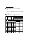
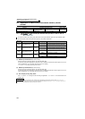
(4) Pulse monitor selection (Pr. 430 )
The status of various pulses during running is displayed.
Set "0" in Pr. 52 DU/PU main display data selection to display output frequency monitor.
Pr. 430
Setting
Description
Display Range
(FR-DU07)
Display Range
(FR-PU04/FR-PU07)
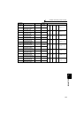
0
The cumulative command pulse value is displayed.
Lower 4 digits Lower 5 digits
1 Upper 4 digits Upper 5 digits
2
The cumulative feedback pulse value is displayed.
Lower 4 digits Lower 5 digits
3 Upper 4 digits Upper 5 digits
4
The droop pulses are monitored.
Lower 4 digits Lower 5 digits
5 Upper 4 digits Upper 5 digits
9999 Frequency monitor is displayed. (initial value)
REMARKS
⋅ Count the number of pulses when the servo is ON.
⋅ The cumulative pulse value is cleared when the base is shut off or the clear signal (CLR) is turned ON.
CAUTION
⋅ Changing the terminal assignment using Pr. 178 to Pr. 189 (input terminal function selection) may affect the other functions. Set
parameters after confirming the function of each terminal.
♦Parameters referred to♦
Pr. 52 DU/PU main display data selection Refer to page 253
Pr. 178 to Pr. 189 (input terminal function selection) Refer to page 231
Deviation counter
image
CLR
ON
When Pr. 429 = "0" When Pr. 429 = "1 (initial value)"
Deviation counter
image
CLR
ON
Counter clear while ONCounter clear at the edge of
turning on of the signal