286
Frequency/torque setting by analog
input (terminal 1, 2, 4)
4.21.2 Analog input selection (Pr. 73, Pr. 267)
(1) Selection of analog input specifications
⋅ For the terminals 2, 4 used for analog input, voltage input (0 to 5V, 0 to 10V) or current input (0 to 20mA) can be
selected.
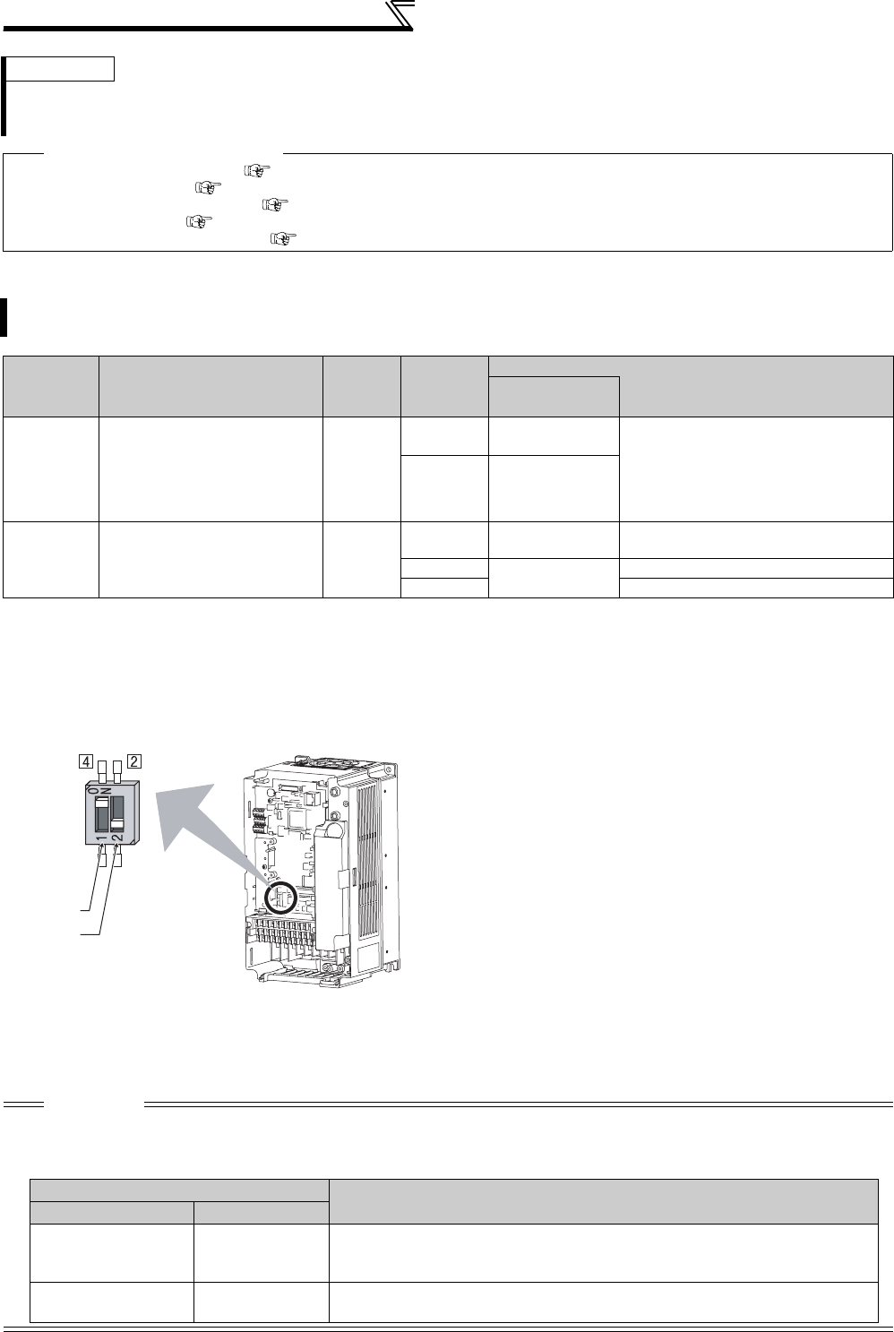
Change parameters (Pr. 73, Pr. 267 ) and a voltage/current input switch (switch 1, 2) to change input specifications.
Switch 1:Terminal 4 input
ON: Current input (initial status)
OFF: Voltage input
Switch 2: Terminal 2 input
ON: Current input
OFF: Voltage input (initial status)
⋅ Rated specifications of terminal 2 and 4 change according to the voltage/current input switch setting.
Voltage input: Input resistance 10kΩ ± 1kΩ, Maximum permissible voltage 20VDC
Current input: Input resistance 245Ω ± 5Ω, Maximum permissible current 30mA
REMARKS
⋅ When "1 or 4" is set in both Pr. 868 and Pr. 858, terminal 1 is valid and terminal 4 has no function.
⋅ When "1" (magnetic flux), "4" (stall prevention/torque limit) is set in Pr. 868, functions of terminal 4 become valid independently
of whether the AU terminal is ON or OFF.
♦ Parameters referred to ♦
Advanced magnetic flux vector control Refer to page 148
Real sensorless vector control Refer to page 92
Pr. 804 Torque command source selection Refer to page 125
Pr. 807 Speed limit selection Refer to page 127
Pr. 810 Torque limit input method selection Refer to page 100
You can select the function that switches between forward rotation and reverse rotation according to the analog
input terminal selection specifications, the override function and the input signal polarity.
Parameter
Number
Name
Initial
Value
Setting
Range
Description
Voltage/current
input switch
73 Analog input selection 1
0 to 5,
10 to 15
Switch 2 - OFF
(initial status)
You can select the input specifications
of terminal 2 (0 to 5V, 0 to 10V, 0 to
20mA) and input specifications of
terminal 1 (0 to ±5V, 0 to ±10V).
Override and reversible operation can
be selected.
6, 7,
16, 17
Switch 2 - ON
267 Terminal 4 input selection 0
0
Switch 1 - ON
(initial status)
Terminal 4 input 0 to 20mA
1
Switch 1 - OFF
Terminal 4 input 0 to 5V
2 Terminal 4 input 0 to 10V
CAUTION
⋅ Set Pr. 73, Pr. 267, and a voltage/current input switch correctly, then input an analog signal in accordance with the setting.
Incorrect setting as in the table below could cause component damage. Incorrect settings other than below can cause abnormal
operation.
Voltage/current
input switch
Switch 1
Switch 2
Setting Causing Component Damage
Operation
Switch setting Terminal input
ON (Current input) Voltage input
This could cause component damage to the analog signal output circuit of
signal output devices.
(electrical load in the analog signal output circuit of signal output devices increases)
OFF (Voltage input) Current input
This could cause component damage of the inverter signal input circuit .
(output power in the analog signal output circuit of signal output devices increases)


