


59
EMC and leakage currents
3
PRECAUTIONS FOR USE OF THE INVERTER
3)Harmonic suppression technique requirement
If the outgoing harmonic current is higher than the maximum value per 1kW (contract power) × contract power, a
harmonic suppression technique is required.
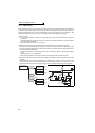
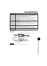
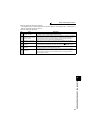
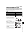
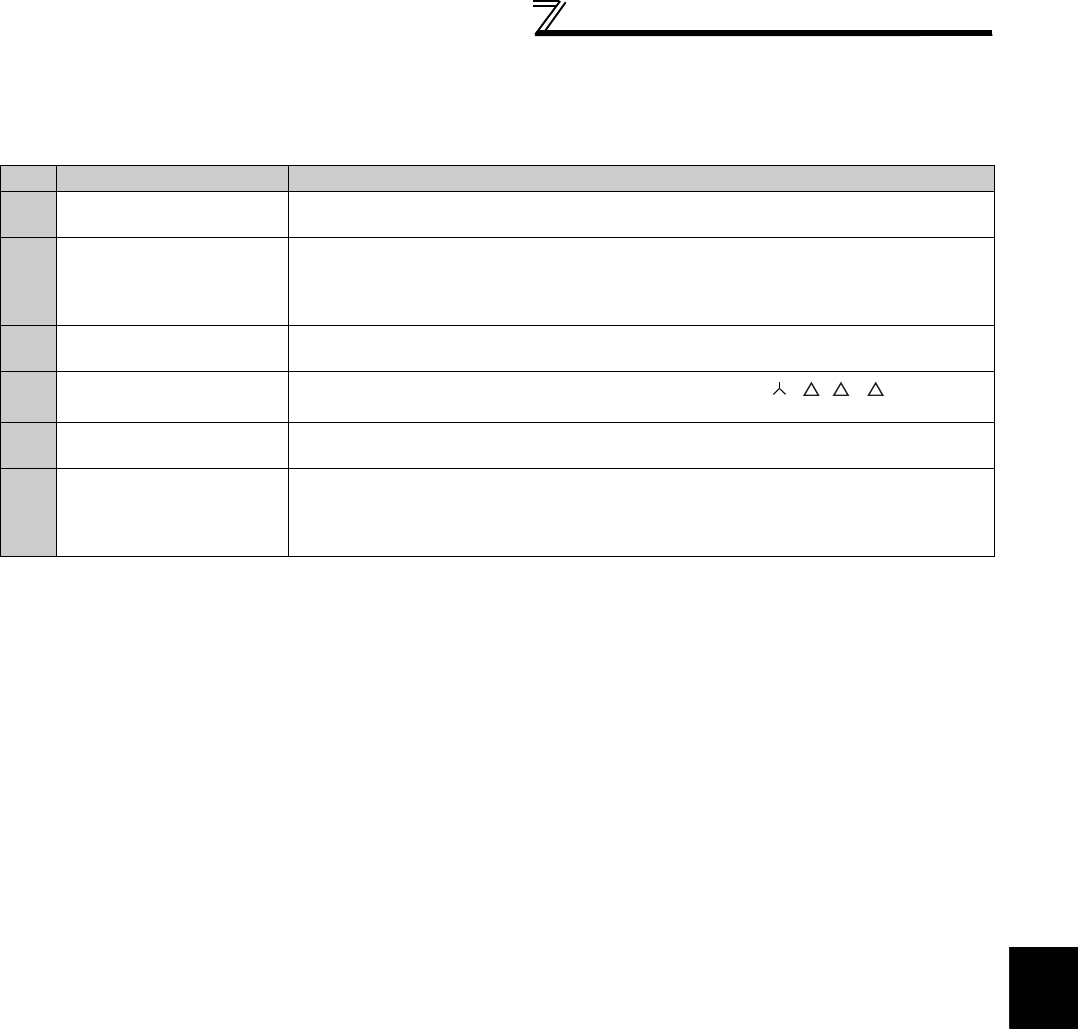
4)Harmonic suppression techniques
No. Item Description
1
Reactor installation
(FR-HAL, FR-HEL)
Install an AC reactor (FR-HAL) on the AC side of the inverter or a DC reactor (FR-HEL) on
its DC side or both to suppress outgoing harmonic currents.
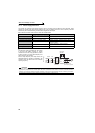
2
High power factor converter
(FR-HC, MT-HC)
This converter trims the current waveform to be a sine waveform by switching in the rectifier
circuit (converter module) with transistors. Doing so suppresses the generated harmonic
amount significantly. Connect it to the DC area of an inverter. The high power factor
converter (FR-HC, MT-HC) is used with the standard accessory.
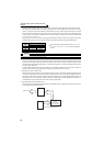
3
Installation of power factor
improving capacitor
When used with a series reactor, the power factor improving capacitor has an effect of
absorbing harmonic currents.
4
Transformer multi-phase
operation
Use two transformers with a phase angle difference of 30° as in - , - combination
to provide an effect corresponding to 12 pulses, reducing low-degree harmonic currents.
5
Passive filter
(AC filter)
A capacitor and a reactor are used together to reduce impedances at specific frequencies,
producing a great effect of absorbing harmonic currents.
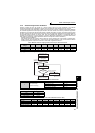
6 Active filter
This filter detects the current of a circuit generating a harmonic current and generates a
harmonic current equivalent to a difference between that current and a fundamental wave
current to suppress a harmonic current at a detection point, providing a great effect of
absorbing harmonic currents.