


40
Connection of stand-alone option units
2.5 Connection of stand-alone option units
The inverter accepts a variety of stand-alone option units as required.
Incorrect connection will cause inverter damage or accident. Connect and operate the option unit carefully in
accordance with the corresponding option unit manual.
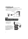
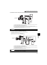
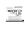
2.5.1 Connection of the dedicated external brake resistor (FR-ABR)
The built-in brake resistor is connected across terminals P/+ and PR. Fit the external dedicated brake resistor (FR-
ABR) when the built-in brake resistor does not have enough thermal capability for high-duty operation (22K or lower).
At this time, remove the jumper from across terminals PR and PX (7.5K or lower)
and connect the dedicated brake
resistor (FR-ABR) across terminals P/+ and PR.
(For the locations of terminal P/+ and PR, refer to the terminal block layout (page 16).)
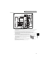
Removing jumpers across terminals PR and PX disables the built-in brake resistor (power is not supplied).
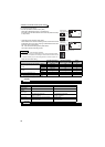
Note that the built-in brake resistor is not need to be removed from the inverter.
The lead wire of the built-in brake resistor is not need to be removed from the terminal.
Set parameters below.
⋅ Pr. 30 Regenerative function selection = "1"
⋅ Pr. 70 Special regenerative brake duty = "7.5K or lower: 10%, 11K or higher: 6%" (Refer to page 207)
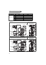
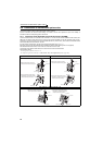
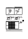
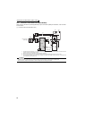
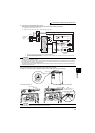
FR-A720-0.4K to 0.75K FR-A720-1.5 to 3.7K, FR-A740-0.4K to 3.7K
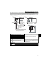
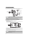
FR-A720-5.5K, 7.5K, FR-A740-5.5K, 7.5K
1) Remove the screws in terminals
PR and PX and remove the jumper.
2) Connect the brake resistor across
terminals P/+ and PR. (The jumper
should remain disconnected.)
Jumper
Terminal PX
Terminal P/+
Terminal PR
Terminal PR
Brake resistor
1) Remove the screws in terminals
PR and PX and remove the jumper.
2) Connect the brake resistor across
terminals P/+ and PR. (The jumper
should remain disconnected.)
Jumper
Terminal PX
Brake resistor
Terminal PR
Terminal PR
Terminal P/+
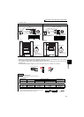
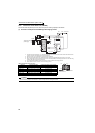
1) Remove the screws in terminals PR
and PX and remove the jumper.
2) Connect the brake resistor across
terminals P/+ and PR. (The jumper
should remain disconnected.)
Jumper
Terminal PX
Terminal PX
Terminal P/+
Terminal PR
Terminal PR
Brake resistor