


306
Misoperation prevention and parameter
setting restriction
(2) Disconnected PU detection
• This function detects that the PU (FR-DU07/FR-PU04/FR-PU07) has been disconnected from the inverter for
longer than 1s and causes the inverter to provide a fault output (E.PUE) and come to trip.
• When Pr. 75 is set to any of "0, 1, 14, 15", operation is continued if the PU is disconnected.
(3) PU stop selection
• In any of the PU operation, External operation and Network operation modes, the motor can be stopped by
pressing of the PU.
• When the inverter is stopped by the PU stop function, " " is displayed. A fault signal output is not provided.
• When Pr. 75 is set to any of "0 to 3", deceleration to a stop by is valid only in the PU operation mode.
(4) How to restart the motor stopped by input from the PU in External operation mode (PU
stop (PS) reset method)
• The motor can be restarted by making a reset using a power supply reset or RES signal.
CAUTION
⋅ When the PU has been disconnected since before power-on, it is not judged as a fault.
⋅ To make a restart, confirm that the PU is connected and then reset the inverter.
⋅ The motor decelerates to a stop when the PU is disconnected during PU jog operation with Pr. 75 set to any of "0, 1, 14, 15"
(operation is continued if the PU is disconnected).
⋅ When RS-485 communication operation is performed through the PU connector, the reset selection/PU stop selection function
is valid but the disconnected PU detection function is invalid.
REMARKS
The motor will also decelerate to a stop (PU stop) when is input during operation in the PU mode through RS-485
communication with Pr. 551 PU mode operation command source selection set to "1" (PU mode RS-485 terminals).
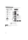
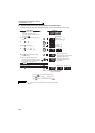
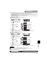
(a) When operation panel (FR- DU07) is used
1)After the motor has decelerated to a stop, turn OFF the
STF or STR signal.
2)Press three times.
(When Pr. 79 Operation mode selection = "0 (initial value)
or 6"••••••( cancel)
Pressing it once cancels when Pr. 79 Operation
mode selection = "2, 3, or 7."
3)Turn ON the STF or STR signal.
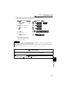
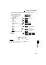
(b)
Connection of the parameter unit (FR-PU04/FR-PU07)
1)After the motor has decelerated to a stop, turn OFF the
STF or STR signal.
2)Press .••••••( canceled)
3)Turn ON the STF or STR signal.
CAUTION
⋅ If Pr. 250 Stop selection is set to other than "9999" to select coasting to a stop, the motor will not be coasted to a stop but
decelerated to a stop by the PU stop function during external operation
CAUTION
Do not reset the inverter with the start signal ON. Doing so will cause the inverter to start immediately after a
reset, leading to hazardous conditions.
♦ Parameters referred to ♦
Pr. 250 Stop selection Refer to page 213
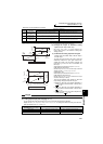
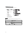
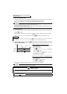
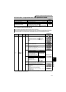
Speed
Time
Key
Key
Stop/restart example for external operation
Operation
panel
STF ON
(STR) OFF
EXT