


47
Connection of stand-alone option units
2
WIRING
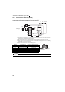
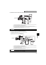
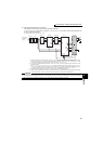
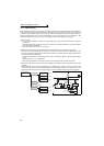
(2) Connection with the MT-HC (75K or higher)
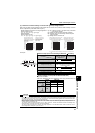
After making sure the wiring is correct, set the following parameters.
Pr. 19 Base frequency voltage (under V/F control) or Pr. 83 Rated motor voltage (under a control method other than V/F
control) = "rated motor voltage"
Pr. 30 Regenerative function selection = "2"
*1 Remove the jumper across terminals R/L1 and R1/L11, S/L2 and S1/L21 of the inverter, and connect the control circuit
power supply to the R1/L11 and S1/L21 terminals. The power input terminals R/L1, S/L2, T/L3 must be open. Incorrect
connection will damage the inverter. (E.OPT (option alarm) will occur. (Refer to page 412.)
*2 Do not insert the MCCB between terminals P/+ and N/- (P and P/+, N and N/-). Opposite polarity of terminals N, P will
damage the inverter.
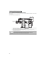
*3 Use Pr. 178 to Pr. 189 (input terminal function selection) to assign the terminals used for the X10 (X11) signal. (Refer to page
231.) For communication where the start command is sent only once, e.g. RS-485 communication operation, use the X11
signal when making setting to hold the mode at occurrence of an instantaneous power failure. (Refer to page 209.)
*4 Connect the power supply to terminals R1 and S1 of the MT-HC via an insulated transformer.
*5 Always connect the terminal RDY (of MT-HC) to a terminal where the X10 or MRS signal is assigned in the inverter. Always
connect the terminal SE (of MT-HC) to the terminal SD (of the inverter). Not doing so may damage MT-HC.
CAUTION
⋅ The voltage phases of terminals R/L1, S/L2, T/L3 and terminals R4, S4, T4 must be matched.
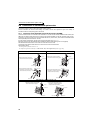
⋅ Use sink logic (factory setting) when the MT-HC is connected. The MT-HC cannot be connected when source logic is selected.
⋅ When connecting the inverter to the MT-HC, do not connect the DC reactor provided to the inverter.
Three-phase
A
C power
supply
MCCB
MT-HCL01 MT-HCB
R1 S1
R1 S1
R1/
L11
S1/
L21
MT-HCL02 MT-HC Inverter
MT-HCTR
Insulated transformer
R
S
T
R/L1
S/L2
T/L3
U
V
W
R2
S2
T2
R2
S2
T2
R3
S3
T3
R3
S3
T3
R4
S4
T4
R4
S4
T4
R
S
T
88R
88S
88R
88S
*2
RDY
RSO
SE
X10
RES
SD
*3
*1
*1
*4
*5
Motor
IM
P
N
P/+
N/
MC