


87
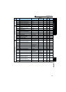
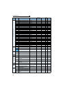
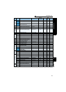
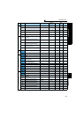
Parameters according to purposes
4
PARAMETERS
(Pr. 74, Pr. 822, Pr. 826, Pr. 832, Pr. 836, Pr. 849) .................................................................................. 292
4.21.5 Bias and gain of frequency setting voltage (current)
(Pr. 125, Pr. 126, Pr. 241, C2(Pr. 902) to C7(Pr. 905), C12(Pr. 917) to C15(Pr. 918))............................. 294
4.21.6 Bias and gain of torque (magnetic flux) setting voltage (current)
(Pr. 241, C16(Pr. 919) to C19(Pr. 920), C38 (Pr. 932) to C41 (Pr. 933)) ................................................ 300
4.22 Misoperation prevention and parameter setting restriction 305
4.22.1 Reset selection/disconnected PU detection/PU stop selection (Pr. 75).................................................... 305
4.22.2 Parameter write selection (Pr. 77)............................................................................................................. 307
4.22.3 Reverse rotation prevention selection (Pr. 78).......................................................................................... 308
4.22.4 Display of applied parameters and user group function (Pr. 160, Pr. 172 to Pr. 174)............................... 308
4.22.5 Password function (Pr. 296, Pr. 297) ........................................................................................................ 310
4.23 Selection of operation mode and operation location 313
4.23.1 Operation mode selection (Pr. 79)............................................................................................................ 313
4.23.2 Operation mode at power ON (Pr. 79, Pr. 340)......................................................................................... 321
4.23.3 Start command source and frequency command source during
communication operation (Pr. 338, Pr. 339, Pr. 550, Pr. 551) .................................................................. 322
4.24 Communication operation and setting 328
4.24.1 Wiring and configuration of PU connector................................................................................................. 328
4.24.2 Wiring and arrangement of RS-485 terminals........................................................................................... 330
4.24.3 Initial settings and specifications of RS-485 communication
(Pr. 117 to Pr. 124, Pr. 331 to Pr. 337, Pr. 341, Pr. 549).......................................................................... 333
4.24.4 Communication EEPROM write selection (Pr. 342).................................................................................. 334
4.24.5 Mitsubishi inverter protocol (computer link communication) ..................................................................... 335
4.24.6 Modbus-RTU communication specifications (Pr. 331, Pr. 332, Pr. 334, Pr. 343,
Pr. 539, Pr. 549)........................................................................................................................................ 347
4.24.7 USB communication (Pr. 547, Pr. 548)..................................................................................................... 360
4.25 Special operation and frequency control 361
4.25.1 PID control (Pr. 127 to Pr. 134, Pr. 575 to Pr. 577)................................................................................... 361
4.25.2 Bypass-inverter switchover function (Pr. 57, Pr. 58, Pr. 135 to Pr. 139, Pr. 159)..................................... 369
4.25.3 Load torque high speed frequency control (Pr. 4, Pr. 5, Pr. 270 to Pr. 274)............................................. 374
4.25.4 Droop control (Pr. 286 to Pr. 288) .......................................................................................................... 376
4.25.5 Frequency setting by pulse train input (Pr. 291, Pr. 384 to Pr. 386)......................................................... 378
4.25.6 Encoder feedback control (Pr. 144, Pr. 285, Pr. 359, Pr. 367 to Pr. 369) ................................................ 381
4.25.7 Regeneration avoidance function (Pr. 665, Pr. 882 to Pr. 886) ................................................................ 383
4.26 Useful functions 385
4.26.1 Cooling fan operation selection (Pr. 244).................................................................................................. 385
4.26.2 Display of the life of the inverter parts (Pr. 255 to Pr. 259)....................................................................... 386
4.26.3 Maintenance timer alarm (Pr. 503, Pr. 504).............................................................................................. 389
4.26.4 Current average value monitor signal (Pr. 555 to Pr. 557)........................................................................ 390
4.26.5 Free parameter (Pr. 888, Pr. 889)............................................................................................................. 392
4.27 Setting of the parameter unit and operation panel 393
4.27.1 PU display language selection (Pr. 145)................................................................................................... 393
4.27.2 Setting dial potentiometer mode/key lock selection (Pr. 161) ................................................................... 393
4.27.3 Buzzer control (Pr. 990)............................................................................................................................ 395
4.27.4 PU contrast adjustment (Pr. 991).............................................................................................................. 395
4.28 Parameter clear and all parameter clear 396
4.29 Parameter copy and parameter verification 397
4.29.1 Parameter copy......................................................................................................................................... 397
4.29.2 Parameter verification............................................................................................................................... 398
4.30 Check and clear of the faults history 399