


379
Special operation and frequency control
4
PARAMETERS
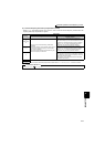
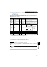
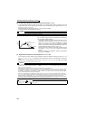
* When the wiring length of the open collector output connection is long, input pulse cannot be recognized because of a pulse shape deformation due to the
stray capacitances of the wiring.
When wiring length is long (10m or more of 0.75mm
2
twisted cable is recommended), connect an open collector output signal and power supply using a pull
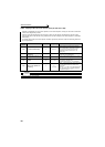
up resistance. The reference of resistance value to the wiring length is as in the table below,
Stray capacitances of the wiring greatly differ according to the cable type and cable laying, the above cable length is not a guaranteed value.
When using a pull up/down resistance, check the permissible power of the resistor and permissible load current of output transistor and use them within a
permissible range.
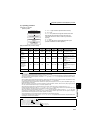
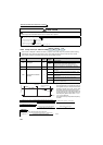
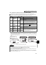
zPulse train input specifications
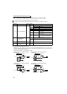
(3) Calculation method of division scaling factor of input pulse (Pr. 384 )
· Maximum input pulse can be calculated from the following formula using Pr. 384 Input pulse division scaling factor.
Maximum of input pulse (pulse/s) = Pr. 384 × 400
(maximum of 100kpulse/s)
(Detectable pulse = 11.45 pulse/s)
· For example, when you want to operate at 0Hz when pulse train input is zero and operate at 30Hz when pulse train
is 4000 pulse/s, set parameters as below.
Pr. 384 = 10
(maximum input pulse 4000 pulse/s)
Pr. 385 = 0Hz, Pr. 386 = 30Hz
(pulse train limit value is 33Hz)
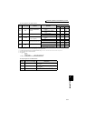
Wiring Length Less than 10m 10 to 50m 50 to 100m
Pull up/down resistance Not necessary 1kΩ 470Ω
Load current (for reference) 10mA 35mA 65mA
REMARKS
· When pulse train input is selected, a function assigned to terminal JOG using Pr. 185 JOG terminal function selection is invalid.
· When Pr. 419 Position command source selection = "2" (simple position pulse train command by inverter pulse train input), JOG
terminal serves as simple position pulse train terminal regardless of the Pr. 291.
CAUTION
· Since Pr. 291 is a selection parameter for pulse train output/FM output, check the specifications of a device connected to
terminal FM when changing the setting value. (Refer to page 259 for pulse train output.)
· Output specifications (high speed pulse train output or FM output) of terminal FM can be selected using Pr. 291. Change the
setting value using care not to change output specifications of terminal FM. (Refer to page 259 for pulse train output.)
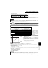
Item Specifications
Available pulse method
Open collector output
Complementary output
(power supply voltage 24V)
* The wiring length of complementary
output depends on the output wiring
specifications of complementary
output device.
Stray capacitances of the wiring
greatly differ according to the cable
type and cable laying, the
maximum cable length is not a
guaranteed value.
H input level 20V or more (voltage between JOG-SD)
L input level 5V or less (voltage between JOG-SD)
Maximum input pulse rate 100kpps
Minimum input pulse width 2.5us
Input resistance/load current 2k
Ω (typ) / 10mA (typ)
Maximum wiring
length
(reference value)
Open collector output system
10m (0.75mm
2
/ twisted pair)
Complementary output system 100m (output resistance 50
Ω) *
Detection resolution 1/3750
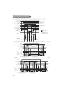
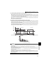
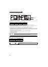
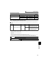
(2) Adjustment of pulse train input and frequency
(Pr. 385, Pr. 386 )
· Frequency for zero input pulse can be set using Pr. 385
Frequency for zero input pulse and frequency at maximum input
pulse can be set using Pr. 386 Frequency for maximum input
pulse.
* Limit value can be calculated from the following formula.
(Pr. 386 - Pr. 385 ) × 1.1 + Pr. 385
REMARKS
The priorities of the frequency commands by the external signals are "Jog operation > multi-speed operation > terminal 4 analog
input > pulse train input".
When pulse train input is valid (when Pr. 291 = "1, 11, 21, or 100" and Pr. 384
≠ "0"), terminal 2 analog input is invalid.
60Hz
Pr. 386
0Hz
Maximum input pulse
Limit value
*
Input pulse
(pulse/s)
(Hz)
Output
frequency
0
Pr. 385