


24
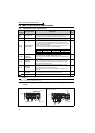
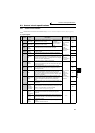
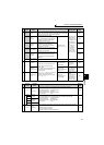
Main circuit terminal specifications
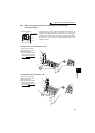
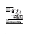
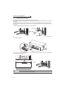
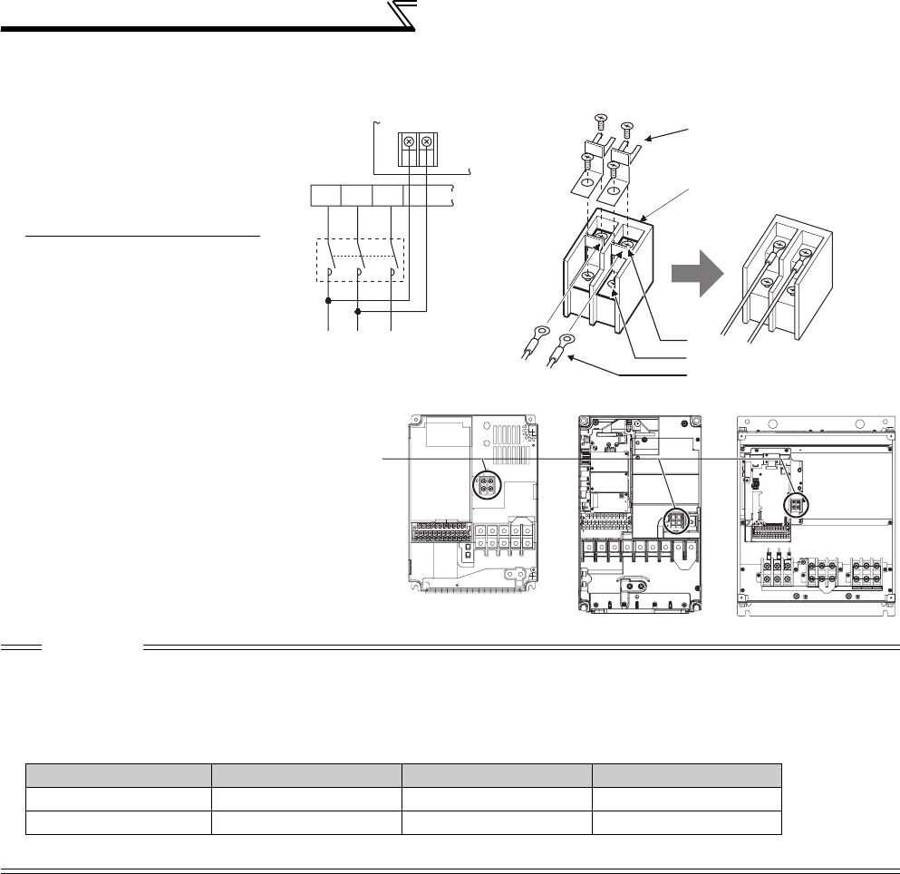
• FR-A720-11K or higher, FR-A740-11K or higher
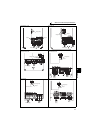
1)Remove the upper screws.
2)Remove the lower screws.
3)Pull the jumper toward you to
remove.
4)
Connect the separate power supply
cable for the control circuit to the
upper terminals (R1/L11, S1/L21)
.
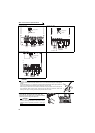
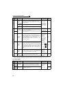
CAUTION
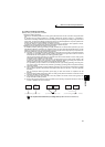
· When using separate power supply, always remove the jumper across terminals R/L1 and R1/L11 and across S/L2 and S1/L21.
The inverter may be damaged if you do not remove the jumper.
· The voltage should be the same as that of the main control circuit when the control circuit power is supplied from other than the
primary side of the MC.
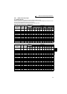
· The power capacity necessary when separate power is supplied from R1/L11 and S1/L21 differs according to the inverter capacity.
· If the main circuit power is switched OFF (for 0.1s or more) then ON again, the inverter resets and a fault output will not be held.
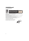
S1/L21
R1/L11
3)
4)
1)
2)
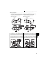
Power supply
terminal block for
the control circuit
Power supply terminal block
for the control circuit
R/L1
S/L2
T/L3
R1/
L11
S1/
L21
Power supply
terminal block
for the control circuit
Main power supply
MC
VUW
FR-A720-11K,
FR-A740-11K, 15K
FR-A720-15K, 18.5K, 22K,
FR-A740-18.5K, 22K
FR-A720-30K or higher,
FR-A740-30K or higher
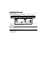
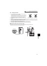
11K or lower 15K 18.5K or higher
200V class
60VA 80VA 80VA
400V class 60VA 60VA 80VA