


412
Causes and corrective actions
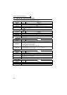
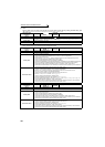
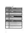
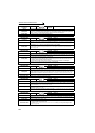
Operation Panel
Indication
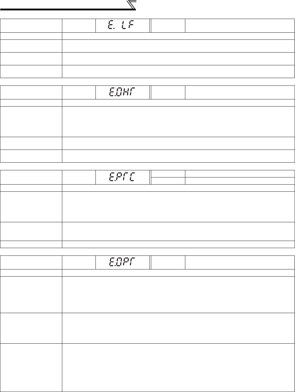
E.LF
FR-PU04
FR-PU07
E.LF
Name
Output phase loss
Description
This function stops the inverter output if one of the three phases (U, V, W) on the inverter's output side
(load side) is lost.
Check point
· Check the wiring (Check that the motor is normal.)
· Check that the capacity of the motor used is not smaller than that of the inverter.
Corrective action
· Wire the cables properly.
· Check the Pr. 251Output phase loss protection selection setting.
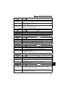
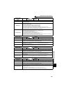
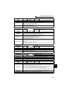
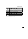
Operation Panel
Indication
E.OHT
FR-PU04
FR-PU07
OH Fault
Name
External thermal relay operation
Description
If the external thermal relay provided for motor overheat protection, or the internally mounted
temperature relay in the motor, etc. switches ON (contacts open), the inverter output is stopped.
This function is available when "7" (OH signal) is set in any of Pr. 178 to Pr. 189 (input terminal function
selection).
When the initial value (without OH signal assigned) is set, this protective function is not available.
Check point
· Check for motor overheating.
·
Check that the value of 7 (OH signal) is set correctly in any of
Pr. 178 to Pr. 189 (input terminal function selection)
.
Corrective action
· Reduce the load and operating duty.
· Even if the relay contacts are reset automatically, the inverter will not restart unless it is reset.
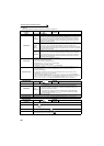
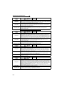
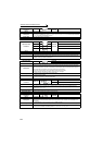
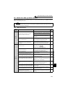
Operation Panel
Indication
E.PTC
FR-PU04 Fault 14
FR-PU07 PTC activated
Name
PTC thermistor operation
Description
Stops the inverter output when the motor overheat status is detected for 10s or more by the external
PTC thermistor input connected to the terminal AU.
This fault is available when "63" is set in Pr. 184 AU terminal function selection and AU/PTC switchover
switch is set in PTC side. When the initial value (Pr. 184 = "4") is set, this protective function is not
available.
Check point
· Check the connection between the PTC thermistor switch and thermal protector.
· Check the motor for operation under overload.
· Is valid setting ( = 63) selected in Pr. 184 AU terminal function selection ? (Refer to page 186, 231.)
Corrective action Reduce the load weight.
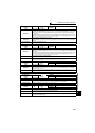
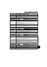
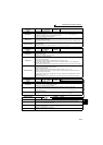
Operation Panel
Indication
E.OPT
FR-PU04
FR-PU07
Option Fault
Name
Option fault
Description
· Appears when the AC power supply is connected to the terminal R/L1, S/L2, T/L3 accidentally when
a high power factor converter is connected.
· Appears when torque command by the plug-in option is selected using Pr. 804 Torque command source
selection and no plug-in option is mounted during torque control.
· Appears when the switch for the manufacturer setting of the plug-in option is changed.
· Appears when a communication option is connected while Pr. 296 = "0 or 100."
Check point
· Check that the AC power supply is not connected to the terminal R/L1, S/L2, T/L3 when a high
power factor converter (FR-HC, MT-HC) or power regeneration common converter (FR-CV) is
connected.
· Check that the plug-in option for torque command setting is connected.
· Check for the password lock with a setting of Pr. 296 = "0, 100"
Corrective action
· Check the parameter (Pr. 30) setting and wiring.
· The inverter may be damaged if the AC power supply is connected to the terminal R/L1, S/L2, T/L3
when a high power factor converter is connected. Please contact your sales representative.
· Check for connection of the plug-in option. Check the Pr. 804 Torque command source selection setting.
· Return the switch for the manufacturer setting of the plug-in option to the initial status. (Refer to
instruction manual of each option)
· To apply the password lock when installing a communication option, set Pr.296 ≠ "0,100". (Refer to
page 310.)