


210
Motor brake and stop operation
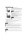
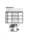
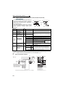
(7) DC feeding mode 2 (Pr. 30 = "20, 21")
⋅ When "20 or 21" is set in Pr. 30, operation is performed with AC power supply normally and with DC power supply
such as battery at power failure.
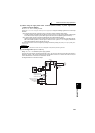
⋅ Connect the AC power supply to terminal R/L1, S/L2, and T/L3 and connect the DC power supply to terminal P/+
and N/-. Also, remove jumpers across terminal R/L1 and R1/L11 as well as S/L2 and S1/L21, and connect
terminals R1/L11 and S1/L21 to terminal P/+ and N/-.
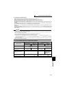
⋅ Turning ON the DC feeding operation permission signal (X70) enables DC power supply operation. Refer to the
table below for I/O signals.
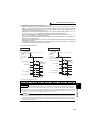
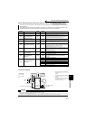
⋅ The following shows the connection diagram when switching to a DC power using inverter power failure detection.
*1 Assign the function using Pr. 178 to Pr. 189 (input terminal function selection).
*2 Assign the function using Pr. 190 to Pr. 196 (output terminal function selection).
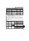
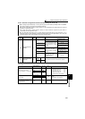
signal Name Description Parameter Setting
Input
X70
DC feeding operation
permission signal
When performing operation with DC feeding, turn
ON the X70 signal.
When the inverter output is shut off because of
power failure, the inverter starts about 150ms
after switching ON X70 signal. (When automatic
restart operation is valid, the inverter starts after
additional Pr. 57 set time has elapsed.)
When the X70 signal turns OFF during inverter
operation, output is shutoff (Pr .261 = 0) or the
inverter is decelerated to a stop (Pr. 261 ≠ 0).
Set 70 in any of Pr. 178 to Pr. 189.
X71 DC feeding cancel signal
Turn this signal ON to stop DC feeding.
When the X71 signal is turned ON during inverter
operation with turning ON the X70 signal, output
is shutoff (Pr. 261 = 0) or the inverter is
decelerated to a stop (Pr. 261 ≠ 0), then the X85
signal turns OFF after the inverter stop.
After turning ON the X71 signal, operation cannot
be performed even if the X70 signal is turned ON.
Set 71 in any of Pr. 178 to Pr. 189.
Output Y85 DC feeding signal
This signal turns ON during power failure or under
voltage of AC power.
The signal turns OFF when the X71 signal turns
ON or power is restored.
The Y85 signal does not turn OFF during inverter
operation even if the power is restored and turns
OFF after an inverter stop.
When the Y85 signal turns ON because of
undervoltage, the Y85 signal does not turn OFF
even if undervoltage is eliminated.
ON/OFF status is retained at an inverter reset.
Set "85 (positive logic) or 185
(negative logic)" in any of Pr. 190
to Pr. 196
DC power
MCCB MC
R/L1
S/L2
T/L3
U
V
W
P/+
N/-
SE
Y85
IM
STF
STR
X70
X71
SD
R1/L11
S1/L21
Earth
(Ground)
10
2
2
3
1
5
(+)
(-)
*1
MC1
MC1
Three-phase AC
power supply
DC feeding permission signal
DC feeding cancel signal
Contact input common
Reverse rotation start
Forward rotation start
*1
*2
Inverter
Inrush
current
limit circuit
Frequency command
Frequency setting
potentiometer
1/2W1kΩ
24VDC
DC feeding signal