


212
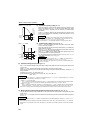
Motor brake and stop operation
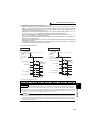
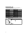
(8) Power supply specification at DC feeding
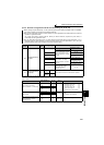
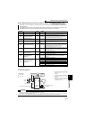
(9) Regenerative brake duty alarm output and alarm signal (RBP signal)
200V class
Rated input DC voltage 283VDC to 339VDC
Permissible fluctuation 240VDC to 373VDC
400V class
Rated input DC voltage 537VDC to 679VDC
Permissible fluctuation 457VDC to 740VDC
CAUTION
⋅ As voltage between P/+, N/- becomes 415V (830V) or more temporarily at regeneration, make selection of DC power supply
carefully.
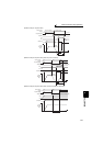
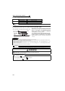
100%: regenerative overvoltage protection operation value
⋅ [RB] appears on the operation panel and an alarm signal
(RBP) is output when 85% of the regenerative brake duty
set in Pr. 70 is reached. If the regenerative brake duty
reaches 100% of the Pr. 70 setting, a regenerative
overvoltage (E.OV1 to E.OV3) occurs.
⋅ The inverter does not trip when the alarm signal is output.
⋅ For the terminal used for the RBP signal output, assign the
function by setting "7" (positive logic) or "107" (negative
logic) in any of Pr. 190 to Pr. 196 (output terminal function
selection).
REMARKS
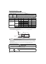
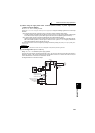
⋅ The MRS signal can also be used instead of the X10 signal. (Refer to page 234.)
⋅ Refer to pages 44 to 48 for the connection of high-duty brake resistor (FR-ABR), brake unit, high power factor converter (FR-HC,
MT-HC) and power regeneration common converter (FR-CV).
⋅ When AC power is connected to terminal R/L1, S/L2, T/L3 during DC feeding with "2, 10 or 11" (DC feeding) set in Pr. 30, an
option fault (E.OPT) occurs.
⋅ When DC feeding operation is performed with "2, 10, 11, 20, or 21" (DC feeding) set in Pr. 30, undervoltage protection (E.UVT)
and instantaneous power failure (E.IPF) are not detected.
CAUTION
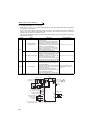
⋅ Changing the terminal assignment using Pr. 178 to Pr. 189 (input terminal function selection) or Pr. 190 to Pr. 196 (output terminal
function selection) may affect the other functions. Set parameters after confirming the function of each terminal. (Refer to page 231)
WARNING
The value set in Pr. 70 must not exceed the setting of the brake resistor used.
Otherwise, the resistor can overheat.
♦ Parameters referred to ♦
Pr. 57 Restart coasting time Refer to page 266
Pr. 178 to Pr.189 (input terminal function selection) Refer to page 231
Pr. 190 to Pr.196 (output terminal function selection) Refer to page 239
Pr. 261 Power failure stop selection Refer to page 270
Ratio of brake duty
to the Pr. 70 setting
Regenerative
brake pre-alarm
(RBP)
OFF
ON
100%
85%
Time
ON