


267
Operation selection at power failure
and instantaneous power failure
4
PARAMETERS
(1) Automatic restart after instantaneous power failure operation
⋅ When instantaneous power failure protection (E.IPF) and undervoltage
protection (E.UVT) are activated, the inverter trips. (Refer to page 411 for
E.IPF and E.UVT.)
When automatic restart after instantaneous power failure operation is set,
the motor can be restarted if power is restored after an instantaneous
power failure or undervoltage is corrected. (E.IPF and E.UVT are not
activated.)
⋅ When E.IPF and E.UVT are activated, instantaneous power failure/under
voltage signal (IPF) is output.
⋅ The IPF signal is assigned to the terminal IPF in the initial setting. The IPF
signal can also be assigned to the other terminal by setting "2 (positive
logic) or 102 (negative logic)" to any of Pr. 190 to Pr. 196 (output terminal
function selection).
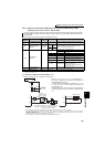
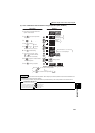
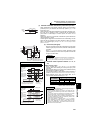
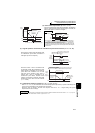
(2) Connection (CS signal)
⋅ When the automatic restart after instantaneous power failure
selection signal (CS) is turned ON, automatic restart operation
is enabled.
⋅ When Pr. 57 is set to other than "9999" (automatic restart
operation enabled), the inverter will not operate if used with the
CS signal remained OFF.
(3) Automatic restart operation selection (Pr. 162, Pr.
299)
With frequency search
When "0 (initial value), 10" is set in Pr. 162, the inverter
smoothly starts after detecting the motor speed upon power
restoration.
⋅ During reverse rotation, the inverter can be restarted smoothly
as the direction of rotation is detected.
⋅ You can select whether to make rotation direction detection or
not with Pr. 299 Rotation direction detection selection at restarting.
When capacities of the motor and inverter differ, set "0"
(without rotation direction detection) in Pr. 299.
ON
Power
supply
OFF
15ms to 100ms
ONIPF
OFF
STF
IM
MCCB
CS
CS
S1/L21
R1/L11
T/L3
S/L2
R/L1
MC1
MC2
MC3
W
V
U
MC
switchover
sequence
SD
SD
For use for only
automatic restart
after instantaneous
power failure or flying start,
short CS and SD in advance.
REMARKS
⋅ The CS signal is assigned to the terminal CS in the initial setting.
By setting "6" in any of Pr. 178 to Pr. 189 (input terminal function
selection), you can assign the CS signal to the other terminal.
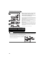
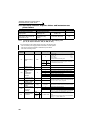
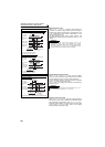
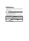
When Pr. 162 = 0, 10 (with frequency search)
V/F control, Advanced magnetic flux vector control
Instantaneous (power failure) time
Power supply
(R/L1, S/L2,
T/L3)
Motor speed N
(r/min)
Inverter output
frequency f(Hz)
Inverter output
voltage E(V)
Coasting
time (Pr.57)
Speed
detection
time
+
Acceleration time
at a restart
(Pr.611 setting)
Restart cushion
time (Pr.58 setting)
*
* The output shut off timing differs
according to the load condition.
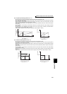
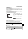
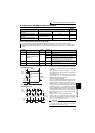
Real sensorless vector control
*
Power supply
(R/L1, S/L2,
T/L3)
Motor speed N
(r/min)
Inverter output
frequency f(Hz)
output voltage
E(V)
Instantaneous (power failure) time
Coasting
time (Pr.57)
Speed
detection
time
+
Acceleration time
at a restart
(Pr.611 setting)
* The output shut off timing differs
according to the load condition.
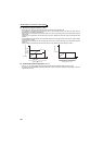
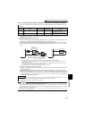
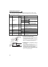
:with rotation direction detection
× :without rotation direction detection
Pr. 299 Setting
Pr. 78 Setting
0 1 2
9999 ××
0 (initial value) ×××
1
REMARKS
⋅ Speed detection time (frequency search) changes according to
the motor speed. (maximum 500ms)
⋅ When the inverter capacity is two rank or more larger than the
motor capacity, the inverter may not start due to overcurrent trip
(E.OC ).
⋅ If two or more motors are connected to one inverter, the inverter
functions abnormally. (The inverter does not start smoothly.)
⋅ Since the DC injection brake is operated instantaneously when
the speed is detected at a restart, the speed may reduce if the
inertia moment (J) of the load is small.
⋅ When reverse rotation is detected when Pr. 78 = "1" (reverse
rotation disabled), the rotation direction is changed to forward
rotation after decelerates in reverse rotation when the start
command is forward rotation. The inverter will not start when the
start command is reverse rotation.