


458
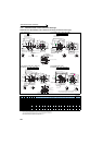
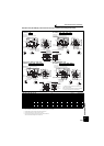
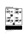
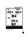
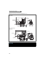
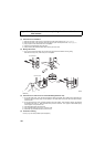
Outline dimension drawings
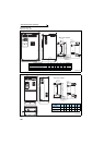
Dedicated motor (SF-THY) outline dimension drawings (1500r/min series)
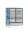
Dimensions table (Unit: mm)
Note) The tolerance of the top and bottom of the center shaft height *C is for the 250 frame and for the 280 frame or more.
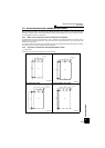
Frame Number 250MD, 280MD
75kW to 160kW
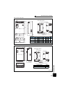
Frame Number 280L, 315H
200kW, 250kW
Output
Frame
No.
Mass
(kg)
Motor Shaft End Size
A B C D E F G H J K K1 K2 L M N R Z XB KA KG Q QK S W T U
75
250MD
610
988.5
340.5
250 557 203
174.5 30
775 100 130 168 50
1471
486 449
482.5
24 168
157.5
635 140 110
φ
75m6
20 12 7.5
90
250MD
660
988.5
340.5
250 557 203
174.5 30
775 100 130
168
50
1471
486 449
482.5
24 168
157.5
635 140 110
φ
75m6
20 12 7.5
110
280MD
870
1049.5
397.5
280 607
228.5 209.5 30
845 110 130 181 40
1619
560 449
569.5
24 190
210.5
705 170 140
φ
85m6
22 14 9
132
280MD
890
1049.5
397.5
280 607
228.5 209.5 30
845 110 130 181 40
1619
560 449
569.5
24 190
210.5
705 170 140
φ
85m6
22 14 9
160
280MD
920
1049.5
397.5
280 607
228.5 209.5
30 845 110 130 181 40
1619
560 499
569.5
24 190
210.5
705 170 140
φ
85m6
22 14 9
200
280L 1170
1210.5
416.5
280 652
228.5 228.5 30
885 110 160
160
75
1799
560 607
588.5
24
190
214.5
745 170 140
φ
85m6
22 14 9
250
315H 1630
1343
565 315 717 254 355
35
965 130 175
428
80
2084
636 870 741
28
216 306 825 170 140
φ
95m6
25 14 9
L
A
R
B
KA
Q
QK
Exhaust
Connector (for encoder)
MS3102A20-29P
Suction
K2
K2
K1
F
FXB
N
K
4-φZ hole
This hole is not used.
PF4 Class B screw
J
EE
S
W
M
H
KG
C
T
U
G
Terminal box for cooling fan
Direction of
cooling fan wind
Terminal box for cooling fan
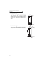
L
A
R
B
K2
K1 K
K2
XB
FF
N
KA
Q
QK
Exhaust
Suction
4-φZ hole
This hole is not used.
PF4 Class B screw
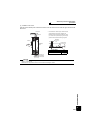
S
W
T
U
H
KG
G
C-
1.0
J
EE
M
0
Connector (for encoder)
MS3102A20-29P
Direction of
cooling fan wind
0
-0.5
0
-1.0