


297
Frequency/torque setting by analog
input (terminal 1, 2, 4)
4
PARAMETERS
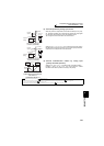
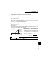
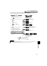
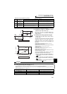
(5) Frequency setting voltage (current) bias/gain adjustment method
(a)Method to adjust any point by application of voltage (current) to across the terminals 2 and 5 (4 and 5).
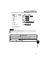
REMARKS
⋅ If the frequency meter (indicator) connected across terminals FM and SD does not indicate exactly 60Hz, set calibration
parameter C0 FM terminal calibration. (Refer to page 263)
⋅ If the gain and bias frequency settings are too close, an error ( ) may be displayed at the time of write.
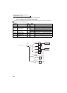
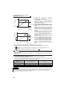
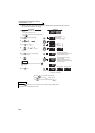
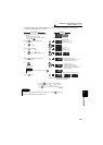
DisplayOperation
Analog voltage (current)
value (%) across terminals 2 and 5
(across terminals 4 and 5)
Flicker...Parameter setting complete!!
*
*
* The value is nearly 100 (%) in the maximum
position of the potentiometer.
* The value is nearly 100 (%) in the maximum
position of the potentiometer.
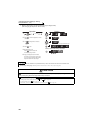
CAUTION
After performing the operation in step 6, do not touch until
completion of calibration.
(Adjustment completed)
Press twice to show the next parameter ( ).
C0 to C41
setting
is enabled.
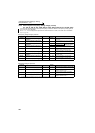
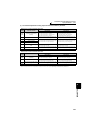
Terminal 2 input Terminal 4 input
Terminal 2 input Terminal 4 input
By turning , you can read another parameter.
Press to return to the display (step 4).
The parameter
number read
previously appears.
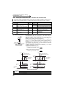
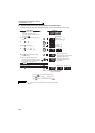
1. Confirm the RUN indicator and operation mode
indicator.
The inverter must be at a stop.
The inverter must be in the PU operation mode.
(Using )
2.Press to choose the parameter setting mode.
3.
Turn until appears.
4. Press to display .
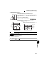
5.
Turn until ( )
appears. Set to
C4 Terminal 2 frequency
setting gain.
6. Press to display the analog voltage (current)
value (%).
7. Apply a 5V (20mA) voltage (current).
(Turn the external potentiometer connected
across terminals 2 and 5 (across terminals 4
and 5) to maximum (any position).)
8.Press to set.