


414
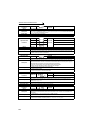
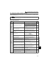
Causes and corrective actions
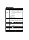
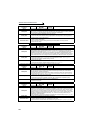
Operation Panel
Indication
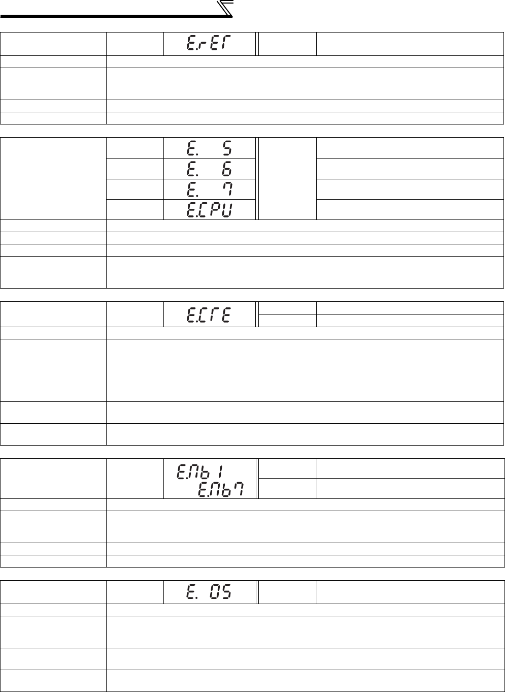
E.RET
FR-PU04
FR-PU07
Retry No Over
Name
Retry count excess
Description
If operation cannot be resumed properly within the number of retries set, this function trips the inverter.
This function is available only when Pr. 67 Number of retries at fault occurrence is set. When the initial value
(Pr. 67 = "0") is set, this fault does not occur.
Check point
Find the cause of alarm occurrence.
Corrective action
Eliminate the cause of the error preceding this error indication.
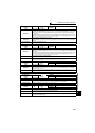
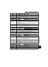
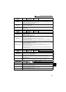
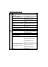
Operation Panel
Indication
E. 5
FR-PU04
FR-PU07
Fault 5
E. 6 Fault 6
E. 7 Fault 7
E.CPU CPU Fault
Name
CPU fault
Description Stops the inverter output if the communication error of the built-in CPU occurs.
Check point Check for devices producing excess electrical noises around the inverter.
Corrective action
· Take measures against noises if there are devices producing excess electrical noises around the
inverter.
· Please contact your sales representative.
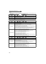
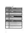
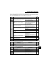
Operation Panel
Indication
E.CTE
FR-PU04
⎯⎯
FR-PU07 E.CTE
Name
Operation panel power supply short circuit, RS-485 terminal power supply short circuit
Description
When the operation panel power supply (PU connector) is shorted, this function shuts off the power
output and stops the inverter. At this time, the operation panel (parameter unit) cannot be used and
RS-485 communication from the PU connector cannot be made. When the internal power supply for
RS-485 terminals are shorted, this function shuts off the power output.
At this time, communication from the RS-485 terminals cannot be made.
To reset, enter the RES signal or switch power OFF, then ON again.
Check point
· Check for a short circuit in the PU connector cable.
· Check that the RS-485 terminals are connected correctly.
Corrective action
· Check the PU and cable.
· Check the connection of the RS-485 terminals
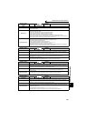
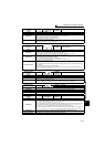
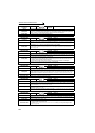
Operation Panel
Indication
E.MB1 to 7
FR-PU04
⎯⎯
FR-PU07 E.MB1 Fault to E.MB7 Fault
Name
Brake sequence fault
Description
The inverter output is stopped when a sequence error occurs during use of the brake sequence
function (Pr. 278 to Pr. 285). This fault is not available in the initial status (brake sequence function is
invalid). (Refer to page 219)
Check point
Find the cause of alarm occurrence.
Corrective action
Check the set parameters and perform wiring properly.
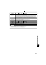
Operation Panel
Indication
E.OS
FR-PU04
FR-PU07
E.OS
Name
Overspeed occurrence
Description
Trips the inverter when the motor speed exceeds the Pr. 374 Overspeed detection level during encoder
feedback control Real sensorless vector control and vector control. This fault is not available in the
initial status.
Check point
· Check that the Pr. 374 Overspeed detection level value is correct.
· Check that the number of encoder pulses does not differ from the actual number of encoder pulses.
Corrective action
·Set the Pr. 374 Overspeed detection level value correctly.
· Set the correct number of encoder pulses in Pr. 369 Number of encoder pulses.
to