


239
Function assignment of external terminal and control
4
PARAMETERS
4.15.6 Output terminal function selection (Pr. 190 to Pr. 196)
.............Specifications differ according to the date assembled. Refer to page 484 to check the SERIAL number.
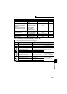
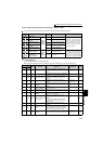
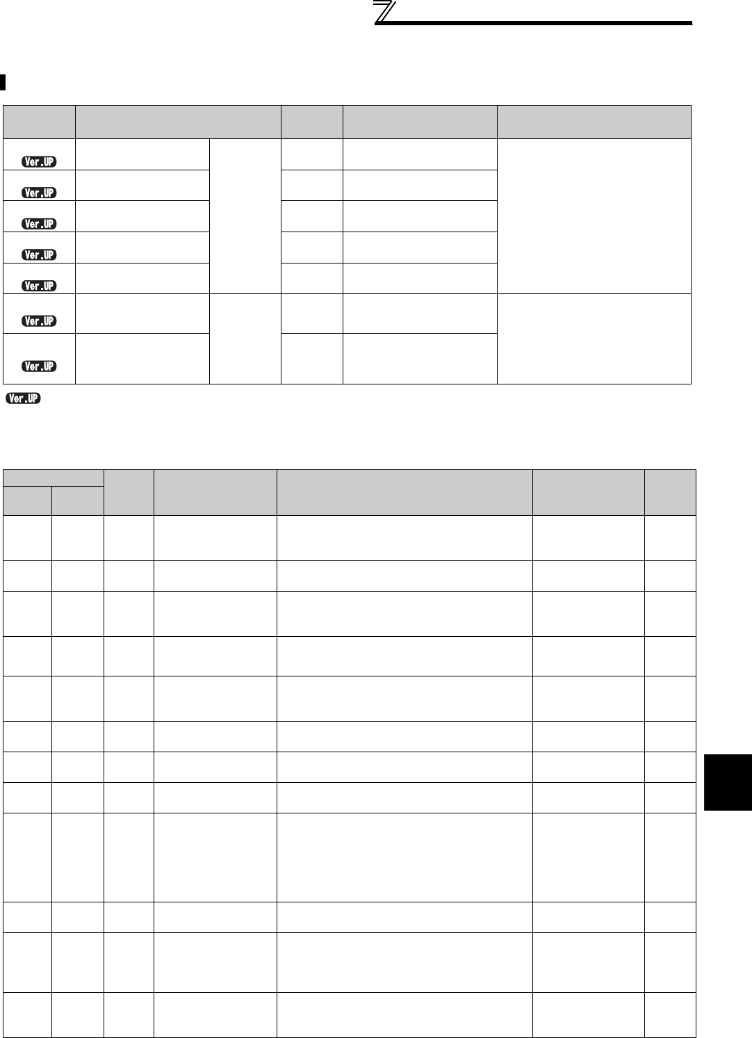
(1) Output signal list
⋅ You can set the functions of the output terminals.
⋅ Refer to the following table and set the parameters: (0 to 99: Positive logic, 100 to 199: Negative logic)
You can change the functions of the open collector output terminal and relay output terminal.
Parameter
Number
Name
Initial
Value
Initial signal Setting Range
190
RUN terminal
function selection
Open
collector
output
terminal
0 RUN (inverter running)
0 to 8, 10 to 20, 25 to 28, 30 to 36,
39, 41 to 47, 55, 64, 70, 83 to 85,
90 to 99, 100 to 108, 110 to 116,
120, 125 to 128, 130 to 136, 139,
141 to 147, 155, 164, 170, 183 to
185, 190 to 199, 9999
191
SU terminal function
selection
1 SU (up to frequency)
192
IPF terminal function
selection
2
IPF (instantaneous power
failure, undervoltage)
193
OL terminal function
selection
3 OL (overload alarm)
194
FU terminal function
selection
4
FU (output frequency
detection)
195
ABC1 terminal
function selection
Relay
output
terminal
99 ALM (fault output)
0 to 8, 10 to 20, 25 to 28, 30 to 36,
39, 41 to 47, 55, 64, 70, 83 to 85,
90, 91, 94 to 99, 100 to 108, 110 to
116, 120, 125 to 128, 130 to 136,
139, 141 to 147, 155, 164, 170, 183
to 185, 190, 191, 194 to 199, 9999
196
ABC2 terminal
function selection
9999 No function
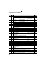
Setting
Signal
Name
Function Operation
Related
Parameters
Refer
to Page
Positive
Logic
Negative
Logic
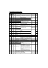
0 100 RUN Inverter running
Output during operation when the inverter
output frequency rises to or above Pr. 13 Starting
frequency.
-242
1 101 SU Up to frequency
*1
Output when the output frequency is reached to
the set frequency.
Pr. 41 246
2102IPF
Instantaneous power
failure/undervoltage
Output at occurrence of an instantaneous power
failure or when undervoltage protection is
activated.
Pr. 57 266
3 103 OL Overload alarm
Output while stall prevention function is
activated.
Pr. 22, Pr. 23,
Pr. 66, Pr. 148,
Pr. 149, Pr. 154
152
4104FU
Output frequency
detection
Output when the output frequency reaches the
frequency set in Pr. 42 (Pr. 43 for reverse
rotation).
Pr. 42, Pr. 43 246
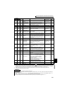
5105FU2
Second output
frequency detection
Output when the output frequency reaches the
frequency set in Pr. 50.
Pr. 50 246
6106FU3
Third output frequency
detection
Output when the output frequency reaches the
frequency set in Pr. 116.
Pr. 116 246
7107RBP
Regenerative brake
pre-alarm
Output when 85% of the regenerative brake
duty set in Pr. 70 is reached.
Pr. 70 207
8108THP
Electronic thermal O/L
relay pre-alarm
Output when the electronic thermal relay
function cumulative value reaches 85% of the
trip level.
(Electronic thermal relay function protection
(E.THT/E.THM) activates, when the value
reached 100%.)
Pr. 9 185
10 110 PU PU operation mode
Output when the PU operation mode is
selected.
Pr. 79 313
11 111 RY
Inverter operation
ready
Output when the inverter power is turned ON,
then output after reset process is completed
(when the inverter can be started by switching
the start signal ON or while it is running).
-242
12 112 Y12
Output current
detection
Output when the output current is higher than
the Pr. 150 setting for longer than the time set in
Pr. 151.
Pr. 150, Pr. 151 248