


380
Special operation and frequency control
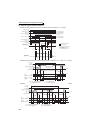
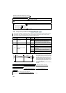
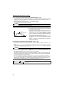
(4) Synchronous speed operation by pulse I/O
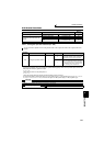
* When the wiring length between FM and JOG is long, a pulse shape is deformed due to the stray capacitances of the wiring and input pulse cannot be
recognized.
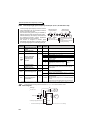
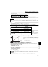
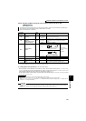
When wiring length is long (10m or more of 0.75mm
2
twisted cable is recommended), connect terminal JOG and terminal PC using an external pull up
resistance. The reference of resistance value to the wiring length is as in the table below.
Stray capacitances of the wiring greatly differ according to the cable type and cable laying, the above cable length is not a guaranteed value.
When using a pull up resistance, check the permissible power and permissible load current (terminal PC : 100mA, high speed pulse train output : 85mA) of the
resistor and use them within a permissible range.
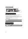
· By setting "100" in Pr. 291, pulse train input can be output at pulse train output (terminal FM) as it is.
Synchronous speed operation of multiple inverters can be enabled by daisy chain connection.
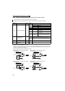
· Since maximum pulse train output is maximum of 50k pulse/s, set "125" in Pr. 384 of the inverter receiving pulse train.
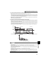
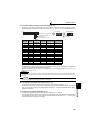
· When operating two or more inverters synchronously, perform wiring according to the following steps. (so that 24V
contact input will not be applied to terminal FM)
1) Set pulse train output (a value other than "0, 1") in Pr. 291 of the master side inverter.
2) Turn OFF the inverter power
3) Perform wiring of the master side terminal FM-SD and slave side terminal JOG-SD
4) Turn ON the inverter power
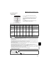
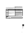
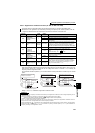
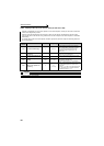
zSpecifications of synchronous speed operation
* When a pulse transmission delay in a slave is approximately 1 to 2μs and wiring length is long, the delay further increases.
Wiring Length Less than 10m 10m to 50m 50m to 100m
Pull up resistance Not necessary 1kΩ 470Ω
Load current (for
reference)
10mA 35mA 65mA
CAUTION
· After changing a setting value of Pr. 291, connect JOG terminal between terminal FM and SD. Take note that a voltage should
not be applied to terminal FM specially when FM output (voltage output) pulse train is selected.
· For the slave side inverter, use sink logic (factory setting). The inverter will not function properly if source logic is selected.
Item Specifications
Output pulse type Pulse width is fixed (10μs)
Pulse rate 0 to 50kpps
Pulse transmission delay 1 to 2μs per inverter *
♦ Parameters referred to ♦
Pr. 291 (pulse train output ) Refer to page 259
Pr. 419 (Position command source selection) Refer to page 137
Pulse train
input
Inverter (master) To next inverter (slave)
To next inverter (slave)
FM
SD
FM
SD
JOG
PC
JOG
SD
Speed
command
Pulse train
output
Pull up
resistance*
Pulse train
output
Speed
command