


249
Function assignment of external terminal and control
4
PARAMETERS
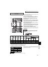
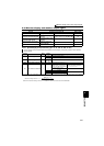
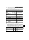
4.15.9 Detection of output torque (TU signal, Pr. 864)
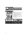
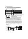
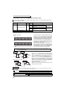
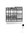
(2) Zero current detection (Y13 signal, Pr. 152, Pr. 153)
⋅ If the output current remains lower than the Pr. 152 setting
during inverter operation for longer than the time set in Pr.
153, the zero current detection (Y13) signal is output from
the inverter's open collector or relay output terminal.
⋅ When the inverter's output current falls to "0", torque will not
be generated. This may cause a drop due to gravity when
the inverter is used in vertical lift application. To prevent this,
the Y13 signal can be output from the inverter to close the
mechanical brake when the output current has fallen to
"zero".
⋅ Set "13 (positive logic)" or "113 (negative logic)" in any of Pr.
190 to Pr. 196 (output terminal function selection) to assign the
function of the Y13 signal to the output terminal.
CAUTION
⋅ This function is also valid during execution of the online or offline auto tuning.
⋅ The response time of Y12 and Y13 signals is approximately 0.1s. Note that the response time changes according to the load
condition.
⋅ When Pr. 152 = "0", detection is disabled.
⋅ When terminal assignment is changed using Pr. 190 to Pr. 196 (output terminal function selection), the other functions may be
affected. Set parameters after confirming the function of each terminal.
CAUTION
The zero current detection level setting should not be too low, and the zero current detection time setting not too
long. Otherwise, the detection signal may not be output when torque is not generated at a low output current.
To prevent the machine and equipment from resulting in hazardous conditions by use of the zero current
detection signal, install a safety backup such as an emergency brake.
♦ Parameters referred to ♦
Online auto tuning Refer to page 199
Offline auto tuning Refer to page 189
Pr. 190 to Pr. 196 (output terminal function selection) Refer to page 239
Output the signal when the motor torque rises above the setting value.
This function can be used for electromagnetic brake operation, open signal, etc.
Parameter
Number
Name Initial Value Setting Range Description
864 Torque detection
150% 0 to 400%
Set the torque value where the TU
signal turns ON.
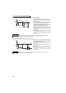
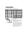
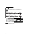
⋅ When the output torque reaches or exceeds the
detected torque value set in Pr. 864 under Real
sensorless vector control, Advanced magnetic flux
vector control or vector control, the torque detection
signal (TU) turns ON.
It turns OFF when the torque falls below the detection
torque value.
⋅ For the TU signal, set "35 (positive logic) or 135
(negative logic)" in Pr. 190 to Pr. 196 (output terminal
function selection) and assign functions to the output
terminal.
CAUTION
⋅ When terminal assignment is changed using Pr. 190 to Pr. 196 (output terminal function selection), the other functions maybe
affected. Set parameters after confirming the function of each terminal.
♦ Parameters referred to ♦
Pr. 190 to Pr. 196 (output terminal function selection) Refer to page 239
OFF ON
Start signal
Time
Output
current
OFF
ON
Zero current
detection time
(Y13)
Pr. 153
Detection time
Pr. 153
Detection time
Pr.152
OFF
ON
0[A]
0.1s*
Pr.152
* Once turned ON, the zero current detection time
signal (Y13) is held ON for at least 0.1s.
Pr. 167 = 0 or 1
Sensorless
Sensorless
Sensorless
Magnetic flux
Magnetic flux
Magnetic flux
Vector
Vector
Vector
Output torque (%)
Time
ONTU OFF
Pr.864