


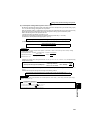

287
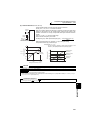
Frequency/torque setting by analog
input (terminal 1, 2, 4)
4
PARAMETERS
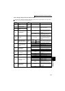
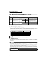
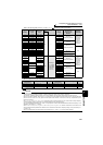
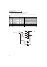
⋅ Refer to the following table and set Pr. 73 and Pr. 267. ( indicates the main speed setting)
⎯ : Invaild
⋅ Set the voltage/current input switch referring to the table below.
Pr. 73
Setting
Terminal 2
Input
Terminal 1
Input
Terminal 4 Input
Pr. 73
Setting
Compensation Input
Terminal and
Compensation
Method
Polarity
Reversible
AU
signal
0 0 to 10V 0 to ±10V
Off ⎯
0
Terminal 1
Added compensation
No
(Indicates that
a frequency
command
signal of
negative
polarity is not
accepted.)
1
(
initial value
)
0 to to 5V 0 to ±10V
1
(initial value)
2
0 to 10V 0 to ±5V 2
3
0 to 5V 0 to ±5V 3
4 0 to 10V
0 to ±10V 4
Terminal 2
Override
50 to 5V
0 to ±5V 5
6
0 to 20mA 0 to ±10V 6
Terminal 1
Added compensation
7
0 to 20mA 0 to ±5V 7
10
0 to 10V 0 to ±10V 10
Yes
11
0 to 5V 0 to ±10V 11
12
0 to 10V 0 to ±5V 12
13
0 to 5V 0 to ±5V 13
14 0 to 10V
0 to ±10V 14
Terminal 2
Override
15 0 to 5V
0 to ±5V 15
16
0 to 20mA 0 to ±10V 16
Terminal 1
Added compensation
17
0 to 20mA 0 to ±5V 17
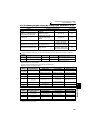
0
⎯
0 to ±10V
On
According to
Pr. 267 setting
0: 4 to 20mA
(
initial value
)
1: 0 to 5V
2: 0 to 10V
0
Terminal 1
Added compensation
No
(Indicates that
a frequency
command
signal of
negative
polarity is not
accepted.)
1 (initial
value)
0 to ±10V
1
(initial value)
2 0 to ±5V 2
3 0 to ±5V 3
4 0 to 10V
⎯
4
Terminal 2
Override
50 to 5V 5
6
⎯
0 to ±10V 6
Terminal 1
Added compensation
7 0 to ±5V 7
10
⎯
0 to ±10V 10
Yes
11 0 to ±10V 11
12 0 to ±5V 12
13 0 to ±5V 13
14 0 to 10V
⎯
14
Terminal 2
Override
15 0 to 5V 15
16
⎯
0 to ±10V 16
Terminal 1
Added compensation
17 0 to ±5V 17
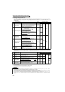
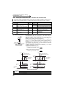
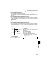
Terminal 2 Input
Specifications
Pr. 73 Setting Switch 2
Terminal 4 Input
Specifications
Pr. 267 Setting Switch 1
Voltage input (0 to 10V) 0, 2, 4, 10, 12, 14 OFF Voltage input (0 to 10V) 2 OFF
Voltage input (0 to 5V) 1 (initial value), 3, 5, 11, 13, 15 OFF Voltage input (0 to 5V) 1 OFF
Current input (0 to 20mA) 6, 7, 16, 17 ON Current input (4 to 20mA) 0 (initial value) ON
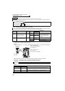
CAUTION
⋅ Turn the AU signal ON to make terminal 4 valid.
⋅ Match the setting of parameter and switch. A different setting may cause a fault, failure or malfunction.
⋅ The terminal 1 (frequency setting auxiliary input) signal is added to the main speed setting signal of the terminal 2 or 4.
⋅ When an override is selected, the terminal 1 or 4 is used for the main speed setting and the terminal 2 for the override signal
(50% to 150% at 0 to 5V or 0 to 10V). (When the main speed of the terminal 1 or terminal 4 is not input, compensation by the
terminal 2 is invalid.))
⋅ Use Pr. 125 (Pr. 126) (frequency setting gain) to change the maximum output frequency at input of the maximum output frequency
command voltage (current). At this time, the command voltage (current) need not be input.
Also, the acceleration/deceleration time, which is a slope up/down to the acceleration/deceleration reference frequency, is not
affected by the change in Pr. 73 setting.
⋅ When Pr. 858 Terminal 4 function assignment, Pr. 868 Terminal 1 function assignment = "4", the value of the terminal 1 or terminal 4 is as
set to the stall prevention operation level. When terminal 1 and terminal 4 are used for frequency setting, set "0" (initial value) in Pr.
858 and Pr. 868.
⋅ When the voltage/current input specifications were changed using Pr. 73 and Pr. 267, be sure to make calibration.
indicates an initial value.