


234
Function assignment of external terminal and control
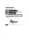
4.15.2 Inverter output shutoff signal (MRS signal, Pr. 17)
The inverter output can be shut off from the MRS signal. The logic of the MRS signal can also be selected.
Parameter
Number
Name
Initial
Value
Setting
Range
Description
17 MRS input selection 0
0 Normally open input
2 Normally closed input (NC contact input specifications)
4
External terminal: Normally closed input
(NC contact input specifications)
Communication: Normally open input
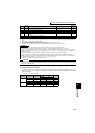
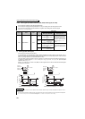
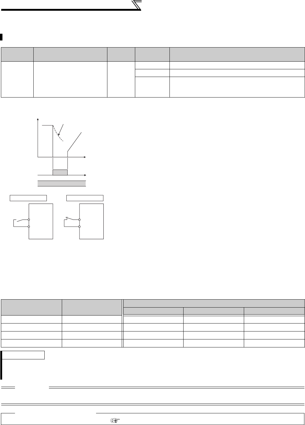
(1) Output shutoff signal (MRS signal)
⋅ Turning on the output shutoff signal (MRS) during inverter running shuts
off the output immediately.
⋅ Terminal MRS may be used as described below.
(a)When mechanical brake (e.g. electromagnetic brake) is used to stop
motor
The inverter output is shut off when the mechanical brake operates.
(b)To provide interlock to disable operation by the inverter
With the MRS signal ON, the inverter cannot be operated if the start
signal is entered into the inverter.
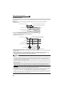
(c) Coast the motor to a stop
When the start signal is turned OFF, the inverter decelerates the
motor to a stop in the preset deceleration time, but when the MRS
signal is turned ON, the motor coasts to a stop
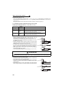
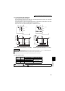
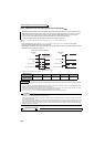
(2) MRS signal logic inversion (Pr. 17 = "2")
⋅ When Pr. 17 is set to "2", the MRS signal (output stop) can be changed
to the normally closed (NC contact) input specification. When the MRS
signal turns ON (opens), the inverter shuts off the output.
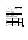
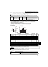
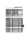
(3) Assign a different action for each MRS signal input from communication and external terminal
(
Pr. 17
= "4")
⋅ When Pr. 17 is set to "4", the MRS signal from external terminal (output stop) can be changed to the normally
closed (NC contact) input, and the MRS signal from communication can be changed to the normally open (NO
contact) input.
This function is useful to perform operation by communication with MRS signal from external terminal remained
ON.
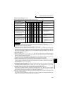
External MRS Communication MRS
Pr. 17 Setting
0 2 4
OFF OFF
Operation enabled Output shutoff Output shutoff
OFF ON Output shutoff Output shutoff Output shutoff
ON OFF
Output shutoff Output shutoff Operation enabled
ON ON
Output shutoff Operation enabled Output shutoff
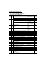
REMARKS
⋅ The MRS signal is assigned to the terminal MRS in the initial setting. By setting "24" in any of Pr. 178 to Pr. 189 (input terminal
function selection), the MRS signal can be assigned to the other terminal.
⋅ When using an external terminal to input the MRS signal, the MRS signal shuts off the output in any of the operation modes.
CAUTION
⋅ Changing the terminal assignment using Pr. 178 to Pr. 189 (input terminal function selection) may affect the other functions. Set
parameters after confirming the function of each terminal.
♦ Parameters referred to ♦
Pr. 178 to Pr. 189 (Input terminal function selection) Refer to page 231
ON
ON
MRS signal
STF (STR)
signal
Motor coasts
to stop
Time
(Initial
value)
Output
stop
Output
stop
MRS
Inverter
MRS
Inverter
Setting value "0"
Setting value "2"
SD SD