


365
Special operation and frequency control
4
PARAMETERS
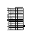
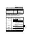
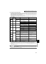
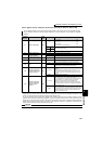
(4) I/O signals and parameter setting
⋅ Turn ON the X14 signal to perform PID control. When this signal is OFF, PID action is not performed and normal
inverter operation is performed. (Note that it is not necessary to turn ON X14 signal when performing PID control
with using LONWORKS or CC-Link communication. )
⋅ Enter the set point across inverter terminals 2 and 5 or into Pr. 133 and enter the measured value signal across
inverter terminals 4 and 5. At this time, set "20" or "21" in Pr. 128.
⋅ When entering the externally calculated deviation signal, enter it across terminals 1 and 5. At this time, set "10" or
"11" in Pr. 128.
Signal
Terminal
Used
Function Description Parameter Setting
Input
X14
Depending on
Pr. 178 to Pr.
189
PID control selection
Turn ON X14 to perform PID control. Set 14 in any of Pr. 178 to Pr. 189.
X64
PID forward/
reverse action
switchover
By turning ON X64, forward action can be
selected for PID reverse action (
Pr. 128
=
10, 20), and reverse action for forward
action (
Pr. 128
= 11, 21).
Set 64 in any of Pr. 178 to Pr. 189.
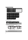
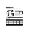
22
*4 Set point input
Enter the set point for PID control. Pr. 128 = 20, 21, Pr. 133 = 9999
0 to 5V............... 0 to 100%
Pr. 73 = 1 *1, 3, 5, 11, 13, 15
0 to 10V............. 0 to 100%
Pr. 73 = 0, 2, 4, 10, 12, 14
0 to 20mA.......... 0 to 100%
Pr. 73 = 6, 7, 16, 17
PU ⎯ Set point input
Set the set value (Pr. 133) from the
operation panel or parameter unit.
Pr. 128 = 20, 21, Pr. 133 = 0 to 100%
11
Deviation signal
input
Input the deviation signal calculated
externally.
Pr. 128 = 10 *1, 11
-5V to +5V......... -100% to +100%
Pr. 73 = 2, 3, 5, 7, 12, 13, 15, 17
-10V to +10V..... -100% to +100%
Pr. 73
= 0, 1
*1
, 4, 6, 10, 11, 14, 16
44 *4
Measured value
input
Input the signal from the detector
(measured value signal).
Pr. 128 = 20, 21
4 to 20mA.0 to 100%
Pr. 267 = 0 *1
0 to 5V......0 to 100%
Pr. 267 = 1
0 to 10V....0 to 100%
Pr. 267 = 2
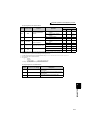
Commu-
nication
*2
⎯
Deviation value
input
Input the deviation value from
L
ONWORKS
,
CC-Link communication.
Pr. 128 = 50, 51
Set value, measured
value input
Input the set value and measured value from
LONWORKS
,
CC-Link communication
.
Pr. 128 = 60, 61
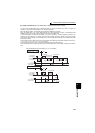
Output
FUP
Depending on
Pr. 190 to Pr.
196
Upper limit output
Output to indicate that the measured
value signal exceeded the maximum
value (Pr. 131).
Pr. 128 = 20, 21, 60, 61
Pr. 131 ≠ 9999
Set 15 or 115 in any of
Pr. 190 to Pr. 196
.
*3
FDN Lower limit output
Output when the measured value signal
falls below the minimum value
(Pr. 132)
.
Pr. 128 = 20, 21, 60, 61
Pr. 132 ≠ 9999
Set 14 or 114 in any of
Pr. 190 to Pr. 196
.
*3
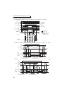
RL
Forward (reverse)
rotation direction
output
"Hi" is output to indicate that the output
indication of the parameter unit is forward
rotation (FWD) or "Low" to indicate that it
is reverse rotation (REV) or stop (STOP).
Set 16 or 116 in any of Pr. 190 to Pr.
196.
*3
PID
During PID control
activated
Turns ON during PID control.
Set 47 or 147 in any of Pr. 190 to Pr.
196.
*3
SLEEP
PID output
interruption
Turns ON when the PID output
interruption function is performed.
Pr. 575 ≠ 9999
Set 70 or 170 in any of
Pr. 190 to Pr. 196
.
*3
SE SE
Output terminal
common
Common terminal for terminals FUP,
FDN, RL, PID and SLEEP
*1 The shaded area indicates the parameter initial value.
*2 For the setting method via L
ONWORKS communication, refer to the LONWORKS communication option (FR-A7NL) instruction manual.
For the setting method via CC-Link communication, refer to the CC-Link communication option (FR-A7NC, FR-A7NCE) instruction manual.
*3 When 100 or larger value is set in any of Pr. 190 to Pr. 196 (output terminal function selection), the terminal output has negative logic. (Refer to page
239 for details)
*4 When the voltage/current input specifications were changed using Pr. 73 and Pr. 267, be sure to make calibration. (Refer to page 367 for
calibration examples for PID control.)
CAUTION
⋅ Changing the terminal function using any of Pr. 178 to Pr. 189, 190 to Pr. 196 may affect the other functions. Set parameters after
confirming the function of each terminal.
⋅ When the Pr. 73 and Pr. 267 settings were changed, check the voltage/current input switch setting. Different setting may cause a
fault, failure or malfunction. (Refer to page 286 for setting.)