


446
Common specifications
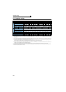
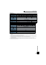
7.3 Common specifications
Control specifications
Control method
Soft-PWM control/high carrier frequency PWM control (V/F control, Advanced magnetic flux vector control and Real sensorless
vector control are available) / vector control
*1
Output frequency range 0.2 to 400Hz (The maximum frequency is 120Hz under Real sensorless vector control and vector control*1.)
Frequency
setting
resolution
Analog input
0.015Hz/60Hz (terminal 2, 4: 0 to 10V/12bit)
0.03Hz/60Hz (terminal 2, 4: 0 to 5V/11bit, 0 to 20mA/about 11bit, terminal 1: 0 to ±10V/12bit)
0.06Hz/60Hz (terminal 1: 0 to ±5V/11bit)
Digital input 0.01Hz
Frequency
accuracy
Analog input Within ±0.2% of the max. output frequency (25°C±10°C)
Digital input Within 0.01% of the set output frequency
Voltage/frequency characteristics Base frequency can be set from 0 to 400Hz Constant torque/variable torque pattern or adjustable 5 points V/F can be selected
Starting torque 200% at 0.3Hz (0.4K to 3.7K), 150% at 0.3Hz (5.5K or higher) (under Real sensorless vector control or vector control *1)
Torque boost Manual torque boost
Acceleration/deceleration time
setting
0 to 3600s (acceleration and deceleration can be set individually), linear or S-pattern acceleration/deceleration mode, backlash
measures acceleration/deceleration mode are available.
DC injection brake Operation frequency (0 to 120Hz), operation time (0 to 10s), operation voltage (0 to 30%) can be changed
Stall prevention operation level Operation current level can be set (0 to 220% adjustable), whether to use the function or not can be selected
Torque limit level Torque limit value can be set (0 to 400% variable)
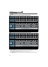
Operation specifications
Frequency
setting
signal
Analog input • Terminal 2, 4: 0 to 10V, 0 to 5V, 4 to 20mA (0 to 20mA) can be selected• Terminal 1: -10 to +10V, -5 to +5V can be selected
Digital input
Input using the setting dial of the operation panel or parameter unit
Four-digit BCD or 16-bit binary (when used with option FR-A7AX)
Start signal Forward and reverse rotation or start signal automatic self-holding input (3-wire input) can be selected.
Input signals (twelve terminals)
The following signals can be assigned to
Pr. 178 to Pr. 189 (input terminal function selection)
: multi speed selection, remote setting, stop-
on-contact, second function selection, third function selection, terminal 4 input selection, JOG operation selection, selection of
automatic restart after instantaneous power failure, flying start, external thermal relay input, inverter run enable signal (FR-HC/FR-CV
connection), FR-HC connection (instantaneous power failure detection), PU operation/external inter lock signal, external DC injection
brake operation start, PID control enable terminal, brake opening completion signal, PU operation/External operation switchover, load
pattern selection forward rotation reverse rotation boost, V/F switching, load torque high-speed frequency, S-pattern acceleration/
deceleration C switchover, pre-excitation, output stop, start self-holding selection, control mode changing, torque limit selection, start-
time tuning start external input, torque bias selection 1, 2
*1
, P/PI control switchover, forward rotation command, reverse rotation
command, inverter reset, PTC thermistor input, PID forward reverse operation switchover, PU-NET operation switchover, NET-
External operation switchover, command source switchover, simple position pulse train sign
*1
, simple position droop pulse clear
*1
,
DC feeding operation permission, DC feeding cancel, magnetic flux decay output shutoff, proximity dog
*3
, 0V calibration request
*5
.
Pulse train input 100kpps
Operational functions
Maximum/minimum frequency setting, frequency jump operation, external thermal relay input selection, polarity reversible operation,
automatic restart after instantaneous power failure operation, electronic bypass operation, forward/reverse rotation prevention,
remote setting, brake sequence, second function, third function, multi-speed operation, original operation continuation at
instantaneous power failure, stop-on-contact control, load torque high speed frequency control, droop control, regeneration
avoidance, slip compensation, operation mode selection, offline auto tuning function, online auto tuning function, PID control,
computer link operation (RS-485), motor end orientation
*1, machine end orientation *2, pre-excitation, notch filter, machine analyzer
*1, easy gain tuning, speed feed forward, and torque bias *1
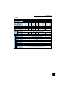
Output signals
Open collector output
(5 terminals)
Relay output (2 terminals)
The following signals can be assigned to Pr. 190 to Pr. 196 (output terminal function selection): inverter running, inverter running/start
command on, up-to-frequency, instantaneous power failure/undervoltage, overload warning, output frequency (speed) detection,
second output frequency (speed) detection, third output frequency (speed) detection, regenerative brake pre-alarm, electronic
thermal relay function pre-alarm, PU operation mode, inverter operation ready, output current detection, zero current detection, PID
lower limit, PID upper limit, PID forward rotation reverse rotation output, electronic bypass MC1, electronic bypass MC2, electronic
bypass MC3, orientation complete
*1, orientation fault *1, brake opening request, fan fault output, heatsink overheat pre-alarm,
deceleration at an instantaneous power failure, PID control activated, motor temperature detection
*4, during retry, PID output
interruption, during 0V calibration
*5, position control preparation ready *1, DC feeding, life alarm, fault output 1, 2, 3 (power-off
signal), power savings average value update timing, current average monitor, maintenance timer alarm, remote output, forward
rotation output
*1, reverse rotation output *1, low speed output, torque detection, regenerative status output *1, start-time tuning
completion, in-position completion
*1, alarm output and fault output. Alarm code of the inverter can be output (4 bit) from the open
collector.
Operating status
When used with the FR-
A7AY, FR-A7AR (option)
In addition to above, the following signal can be assigned to Pr.313 to Pr. 319 (extension output terminal function selection): control circuit
capacitor life, main circuit capacitor life, cooling fan life, inrush current limit circuit life. (only positive logic can be set for extension
terminals of the FR-A7AR)
Pulse train output 50kpps
For meter
Pulse train output
(Max. 2.4kHz: one terminal)
Analog output
(Max. 10VDC: one terminal)
The following signals can be assigned to
Pr. 54 FM terminal function selection (pulse train output)
and
Pr. 158 AM terminal function selection
(analog output)
: output frequency, motor current (steady or peak value), output voltage, frequency setting, operation speed, motor
torque, converter output voltage (steady or peak value), electronic thermal relay function load factor, input power, output power, load
meter, motor excitation current, reference voltage output, motor load factor,
motor temperature *4
, power saving effect, regenerative
brake duty, PID set point, PID measured value, motor output, torque command, torque current command, and torque monitor.
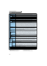
Indication
Operation
panel
(FR-DU07)
Parameter
unit (FR-
PU07)
Operating status
The following operating status can be displayed: Output frequency, motor current (steady or peak value), output voltage, frequency
setting, running speed, motor torque, overload, converter output voltage (steady or peak value), electronic thermal relay function
load factor, input power, output power, load meter, motor excitation current, position pulse *1, cumulative energization time,
orientation status *1, actual operation time, motor load factor, cumulative power, energy saving effect, cumulative saving power,
regenerative brake duty, PID set point, PID measured value, PID deviation, inverter I/O terminal monitor, input terminal option
monitor*6, output terminal option monitor *6, option fitting status *7, terminal assignment status *7, torque command, torque current
command, feed back pulse
*1, motor output, SSCNET III communication status *3, motor temperature *4
Fault record
Fault definition is displayed when a fault occurs, the output voltage/current/frequency/cumulative energization time right before the
fault occurs and past 8 fault records are stored.
Interactive guidance Function (help) for operation guide *7
Protective/
warning
function
Protective function
Overcurrent during acceleration, overcurrent during constant speed, overcurrent during deceleration, overvoltage during
acceleration, overvoltage during constant speed, overvoltage during deceleration, inverter protection thermal operation, motor
protection thermal operation, heatsink overheat, instantaneous power failure occurrence, undervoltage, input phase loss
*10, motor
overload, output side earth (ground) fault overcurrent, output short circuit, main circuit element overheat, output phase loss, external
thermal relay operation
*10, PTC thermistor operation *10, option fault, parameter error, PU disconnection, retry count excess *10,
CPU fault, operation panel power supply short circuit, 24VDC power output short circuit, output current detection value excess
*10,
inrush current limit circuit fault, communication fault (inverter), USB fault, opposite rotation deceleration fault
*10, analog input fault,
brake transistor alarm, speed deviation large
*1*10, overspeed *1*10, position error large *1*10, signal loss detection *1*10, brake
sequence fault
*10, encoder phase error *1*10
Warning function
Fan fault, overcurrent stall prevention, overvoltage stall prevention, regenerative brake pre-alarm *10, electronic thermal relay
function pre-alarm, PU stop, maintenance timer alarm
*10, parameter write error, copy operation error, operation panel lock,
password locked, parameter copy alarm, speed limit indication
Environment
Surrounding air temperature -10°C to +50°C (non-freezing)
Ambient humidity 90%RH maximum (non-condensing)
Storage temperature *8 -20°C to +65°C
Atmosphere Indoors (without corrosive gas, flammable gas, oil mist, dust and dirt etc.)
Altitude/vibration
Maximum 1000m above sea level for standard operation. 5.9m/s
2
or less *9 at 10 to 55Hz (directions of X, Y, Z axes)
*1 Available only when the option (FR-A7AP/FR-A7AL) is mounted.
*2 Available only when the option (FR-A7AL) is mounted.
*3 Available only when the option (FR-A7NS) is mounted.
*4 Available only when the option (FR-A7AZ) is mounted and SF-
V5RUT/A is used.
*5 Available only when the option (FR-A7AD) is mounted.
*6 Can be displayed only on the operation panel (FR-DU07).
*7 Can be displayed only on the parameter unit (FR-PU07).
*8 Temperature applicable for a short period in transit, etc.
*9 2.9m/s
2
or less for the 160K or higher.
*10 This protective function is not available in the initial status.