


38
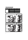
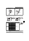
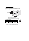
Connection of motor with encoder (vector control)
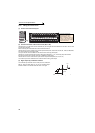
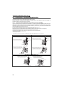
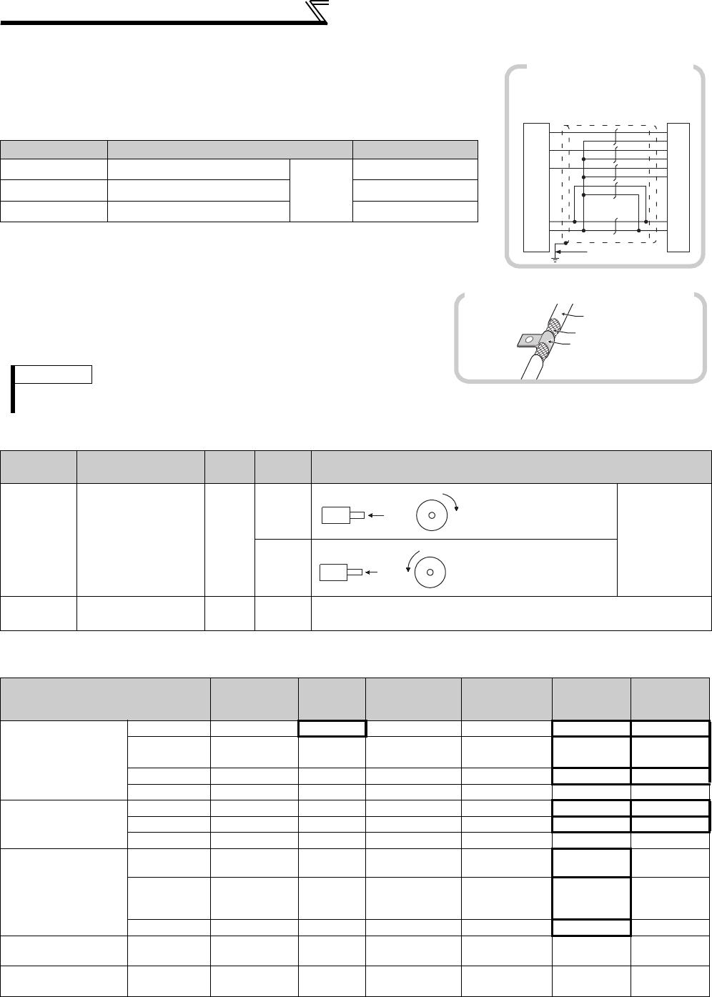
(6) Instructions for encoder cable wiring
• Use shielded twisted pair cables (0.2mm
2
or larger) to connect the FR-A7AP
and position detector. Cables to terminals PG and SD should be connected in
parallel or be larger in size according to the cable length.
To protect the cables from noise, run them away from any source of noise (e.g.
the main circuit and power supply voltage).
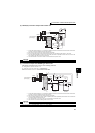
* When differential line driver is set and a wiring length is 30m or more
The wiring length can be extended to 100m by slightly increasing the power by 5V (approx. 5.5V)
using six or more cables with gauge size of 0.2mm
2
in parallel or a cable with gauge size of 1.25mm
2
or more. Note that the voltage applied should be within power supply specifications of encoder.
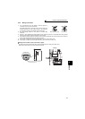
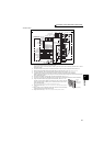
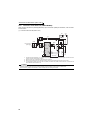
• To reduce noise of the encoder cable, earth (ground) the encoder
shielded cable to the enclosure (as close as possible to the inverter)
with a P-clip or U-clip made of metal.
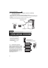
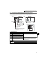
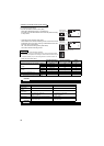
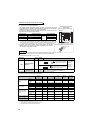
(7) Parameter for encoder (Pr. 359, Pr. 369)
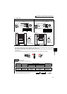
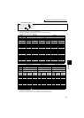
(8) Motor for vector control and parameter setting
Wiring Length Parallel Connection Larger-Size Cable
Within 10m At least two cables in parallel
Cable
gauge
0.2mm
2
0.4mm
2
or larger
Within 20m At least four cables in parallel
0.75mm
2
or larger
Within 100m * At least six cables in parallel
1.25mm
2
or larger
REMARKS
· For details of the optional encoder dedicated cable (FR-JCBL/FR-V7CBL), refer to page 35.
· The FR-V7CBL is provided with a P clip for earthing (grounding) shielded cable.
Parameter
Number
Name
Initial
Value
Setting
Range
Description
359
Encoder rotation
direction
1
0 Set the rotation
direction
according to
the motor
specification.
1
369
Number of
encoder pulses
1024
0 to
4096
Set the number of encoder pulses output.
Set the number of pulses before it is multiplied by 4.
The above parameters can be set when the FR-A7AP/FR-A7AL (option) is mounted.
Motor Name
Pr. 9
Electronic thermal
O/L relay
Pr. 71
Applied motor
Pr. 80
Motor capacity
Pr. 81
Number of motor
poles
Pr. 359
Encoder rotation
direction
Pr. 369
Number of
encoder pulses
Mitsubishi standard
motor
SF-JR
Motor rated current
0 Motor capacity
Number of motor poles
1 1024
SF-JR 4P 1.5kW
or lower
Motor rated current
20 Motor capacity 4 1 1024
SF-HR
Motor rated current
40 Motor capacity
Number of motor poles
1 1024
Others
Motor rated current
3 *1 Motor capacity
Number of motor poles
*2 *2
Mitsubishi constant-
torque motor
SF-JRCA 4P
Motor rated current
1 Motor capacity 4 1 1024
SF-HRCA
Motor rated current
50 Motor capacity
Number of motor poles
1 1024
Others
Motor rated current
13 *1 Motor capacity
Number of motor poles
*2 *2
Mitsubishi vector
control dedicated
motor
SF-V5RU
(1500r/min series)
0 *3 30 Motor capacity 4 1 2048
SF-V5RU
(except for 1500r/
min series)
0 *3 13 *1 Motor capacity 4 1 2048
SF-THY 0
*3 33 *1 Motor capacity 4 1 2048
Other manufacturer's
standard motor
—
Motor rated current
3 *1 Motor capacity
Number of motor poles
*2 *2
Other manufacturer's
constant-torque motor
—
Motor rated current
13 *1 Motor capacity
Number of motor poles
*2 *2
Values in the bolded frame are initial values.
*1 Offline auto tuning is necessary. (Refer to page 189)
*2 Set this parameter according to the motor (encoder) used.
*3 Use thermal protector input provided with the motor.
PZ2
PZ1
PA1
PA2
FB1
FB2
SD
PG
G
F
D
C
B
A
R
S
PLG
2mm
2
FR-A700
(FR-A7AP)
Example of parallel connection
with two cables
(with complementary encoder output)
Encoder cable
Shield
P-clip
Earthing (grounding) example using a P-clip
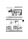
Forward rotation is clockwise
rotation when viewed from A.
A
Encoder
CW
A
Encoder
CCW
Forward rotation is counterclockwis
e
rotation when viewed from A.