


381
Special operation and frequency control
4
PARAMETERS
4.25.6 Encoder feedback control (Pr. 144, Pr. 285, Pr. 359, Pr. 367 to Pr. 369)
(1) Setting before the operation (Pr. 144, Pr. 359, Pr. 369 )
⋅ When performing encoder feedback control under V/F control, set the number of motor poles in Pr. 144 Speed setting
switchover according to the motor used. Because the number of motor poles is set in Pr. 81 Number of motor poles
under Advanced magnetic flux vector control, it is unnecessary to change Pr. 144.
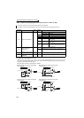
⋅ Set the rotation direction and the number of encoder pulses of the encoder using Pr. 359 Encoder rotation direction and
Pr. 369 Number of encoder pulses.
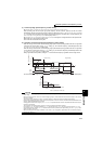
This controls the inverter output frequency so that the motor speed is constant to the load variation by detecting the
motor speed with the speed detector (encoder) to feed it back to the inverter.
Option FR-A7AP/FR-A7AL is necessary.
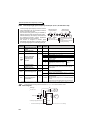
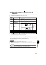
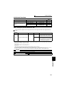
Parameter
Numbers
Name
Initial
Value
Setting Range Description
144
Speed setting
switchover
4
0, 2, 4, 6, 8, 10,
102, 104, 106,
108, 110
Set the number of motor poles when performing encoder
feedback control under V/F control.
285
Overspeed detection
frequency
(Speed deviation excess
detection frequency)
*1
9999
0 to 30Hz
If (detected frequency) - (output frequency) > Pr. 285 during
encoder feedback control, the inverter fault (E.MB1) is
provided.
9999
Overspeed is not detected.
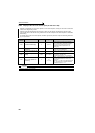
359 *2
Encoder rotation
direction
1
0
Set the rotation
direction according to
the motor
specification.
1
367 *2 Speed feedback range 9999
0 to 400Hz
Set the region of speed feedback control.
9999
Encoder feedback control is invalid
368 *2 Feedback gain 1 0 to 100 Set when the rotation is unstable or response is slow.
369 *2
Number of encoder
pulses
1024 0 to 4096
Set the number of pulses of the encoder.
Set the number of pulses before multiplied by four.
*1 When exercising vector control with the FR-A7AP/FR-A7AL (option), this parameter changes to excessive speed deviation detection frequency.
(For details, refer to page 117)
*2 The above parameters can be set when the FR-A7AP/FR-A7AL (option) is mounted.
REMARKS
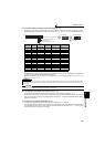
⋅ When "0, 10, 110" is set in Pr. 144 and run the inverter, fault E.1 to E.3 occurs.
⋅ When "102, 104, 106, 108" is set in Pr. 144, the value subtracting 100 is set as the number of motor poles.
⋅ Setting Pr. 81 Number of motor poles changes the Pr. 144 setting automatically. However, changing the Pr. 144 setting will not
change the Pr. 81 setting automatically.
CAUTION
⋅ If the number of motor poles is wrong, control at correct speed cannot be performed. Always check before operation.
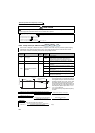
⋅ Encoder feedback control cannot be performed when the setting of encoder rotation direction is wrong. (Inverter operation is
enabled.)
Encoder rotation direction can be checked with the rotation direction display of the parameter unit.
V/F
V/F
V/F
Magnetic flux
Magnetic flux
Magnetic flux
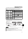
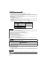
A
Encoder
CW
Clockwise direction as viewed
from A is forward rotation
CCW
A
Encoder
Counter clockwise direction as
viewed from A is forward rotation