


301
Frequency/torque setting by analog
input (terminal 1, 2, 4)
4
PARAMETERS
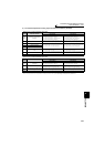
Terminal 4 functional calibration parameter
⎯ : No function
* Use Pr. 148 Stall prevention level at 0V input and Pr. 149 Stall prevention level at 10V input to adjust bias/gain of stall prevention operation level.
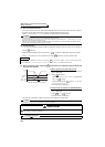
(5) Analog input display unit changing (Pr. 241)
· You can change the analog input display unit (%/V/mA) for analog input bias/gain calibration.
· Display unit of C17 (Pr. 919), C19 (Pr. 920), C39 (Pr. 932), C41 (Pr. 933) changes as follows according to the terminal
input specifications set in Pr. 73 and Pr. 267 .
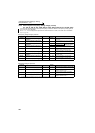
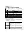
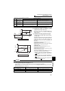
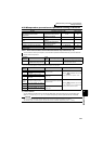
Pr. 858
Setting
Terminal
Function
Calibration Parameters
Bias setting Gain setting
0
(initial
value)
Frequency (speed)
command/speed
limit
C5(Pr. 904) Terminal 4 frequency setting bias frequency
C6(Pr. 904) Terminal 4 frequency setting bias
Pr. 126 Terminal 4 frequency setting gain frequency
C7(Pr. 905) Terminal 4 frequency setting gain
1
Magnetic flux
command
C38(Pr. 932) Terminal 4 bias command (torque/magnetic flux)
C39(Pr. 932) Terminal 4 bias (torque/magnetic flux)
C40(Pr. 933) Terminal 4 gain command (torque/magnetic flux)
C41(Pr. 933) Terminal 4 gain (torque/magnetic flux)
4
Stall prevention
operation level */
torque limit
C38(Pr. 932) Terminal 4 bias command (torque/magnetic flux)
C39(Pr. 932) Terminal 4 bias (torque/magnetic flux)
C40(Pr. 933) Terminal 4 gain command (torque/magnetic flux)
C41(Pr. 933) Terminal 4 gain (torque/magnetic flux)
9999
⎯⎯ ⎯
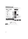
(3) Change the torque at maximum analog
input. (C18(Pr. 920), C40(Pr. 933))
·Set C18(Pr. 920), C40(Pr. 933) when changing only
torque setting (gain) of the maximum analog input
voltage (current).
(4) Calibration of analog input bias and gain
(C16(Pr. 919) to C19(Pr. 920), C38 (Pr. 932) to
C41 (Pr. 933))
· The "bias" and "gain" functions are used to adjust the
relationship between the input signal entered from
outside the inverter to set the torque command and
torque limit, e.g. 0 to 5V, 0 to 10V or 4 to 20mADC, and
the torque.
· Set the bias torque of terminal 1 input in C16 (Pr. 919) .
(Initial value is the torque at 0V)
· Set the torque in C18 (Pr. 920) for the torque command
voltage set with Pr. 73 Analog input selection.
(initial value is 10V)
· Set the bias torque of terminal 4 input in C38 (Pr. 932) .
(Initial value is the torque at 4mA)
· Set the torque in C40 (Pr. 933) for 20mA of the torque
command current (4 to 20mA).
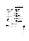
· There are the following three methods to adjust the
torque setting voltage (current) bias and gain.
a) Method to adjust any point without application of
voltage (current) across terminals 1 and 5(4 and 5)
page 302
b) Method to adjust any point without application of
voltage (current) across terminals 1 and 5(4 and 5)
page 303
c) Method to adjust torque only without adjustment of
voltage (current) page 304
CAUTION
· When voltage/current input specifications were switched using Pr. 73 and Pr. 267 , perform calibration without fail.
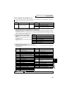
Analog Command (terminal 1,4)
(according to Pr. 73, Pr. 267 )
Pr. 241 = 0 (initial value) Pr. 241 = 1
0 to 5V input 0 to 5V → displayed in 0 to 100% (0.1%) 0 to 100% → displayed in 0 to 5V (0.01V)
0 to 10V input 0 to 10V → displayed in 0 to 100% (0.1%) 0 to 100% → displayed in 0 to 10V (0.01V)
0 to 20mA input 0 to 20mA → displayed in 0 to 100% (0.1%) 0 to 100% → displayed in 0 to 20mA (0.01mA)
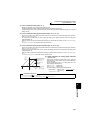
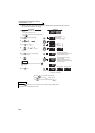
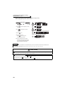
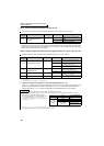
Calibration example of terminal 1
400
150
-150
0
0
Torque setting signal
100%
10V
Bias
05V
(-5V)
-100%
(-10V)
C18(Pr.920)
Gain
C16(Pr.919)
C17(Pr.919) C19(Pr.920)
Torque(%)
Initial value
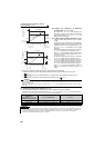
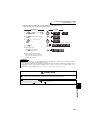
400
150
Torque(%)
0
Torque setting signal
100%
Bias
0
20
4 20mA
C40
(Pr.933)
Gain
C38
(Pr.932)
C39(Pr.932) C41(Pr.933)
Initial value
Calibration example of terminal 4