


Schematic Capture - Basics
4-18 Electronics Workbench
4.4.8 Controlling Component Color
The default color used for a component and the background color of the circuit window are
controlled in the
Sheet Properties dialog box, as described in “3.4.2.1 Sheet Properties -
Circuit Tab” on page 3-24.
To change the color of a placed component, right-click on the component and choose
Color
from the pop-up menu that appears. You are presented with a color palette. Choose a color and
click
OK to apply it to the selected item.
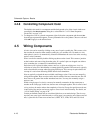
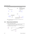
4.5 Wiring Components
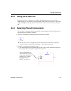
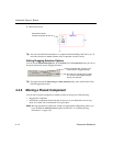
A basic wire can be created by clicking on any one of a part's symbol pins. This creates a wire
that can then be routed to either another symbol pin, or to another wire. If routed to a wire,
when placed a junction is automatically created to differentiate the case of two wires crossing
and two wires connected.
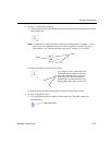
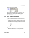
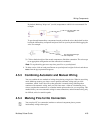
Wires can also be started by double-clicking anywhere on the circuit. This creates a junction
at that location and starts wiring from that point. If a symbol's pins are dropped onto either a
wire or another pin, a connection is automatically made.
Each time a wire is placed it either creates a new net, or joins an existing one. A net is a
collection of wires all of which define a common electrical potential. The term net is typically
used to describe this concept when discussing PCB layout. This concept is equivalent to the
concept of a node when discussing SPICE-based circuit simulation.
Nets are typically assigned the next available small integer value. If two nets are merged by
wiring them together, there are rules used to decide which of the two names the new net will
bear, however in general the smaller-numbered net wins. You may also manually assign a
name to a net.
Within a single-page of a circuit, a net may be manually renamed to be the same name as
another on the same page. In this case, the two nets are merged together. This is called virtual
wiring and may be used to reduce the complexity of circuits. Except for special reserved nets,
virtual wiring may not be used across pages or across levels in the hierarchy. For details, see
“4.5.10 Virtual Wiring” on page 4-28.
Certain pre-defined named nets are considered global across an entire design. That is to say,
anytime a net at any level in the hierarchy or on any page is re-named to one of these reserved
nets, it joins this net. These reserved nets are 0, GND, VCC, VDD, VEE, and VSS. Net 0