


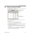

Editing a Component’s Footprint
Multicap 9 User Guide 8-45
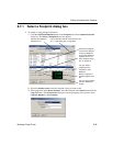
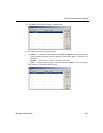
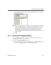
As you change the values in the above two fields, the
Footprint Pins values are updated as
in the example shown below.
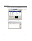
Note BGA pins in Ultiboard (Electronic Workbench’s PCB layout software), are named in a
matrix array starting with A1, A2…Ax; the next row would be B1, B2...Bx, etc. When
creating this symbol in Multisim, the footprint pins are initially named 1, 2, 3 etc… .
The functionality described in this step allows the footprint pins to be renamed to
match the alpha-numeric pin naming method used in Ultiboard. This feature is
especially useful for BGAs with large numbers of pins that would otherwise have to be
manually renamed.
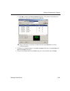
5. Click
OK.
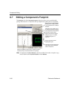
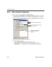
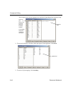
8.7.3 Advanced Pin Mapping Dialog
The Advanced Pin Mapping dialog box is used to map symbol pins to footprint pins and is
especially useful for more complex components.
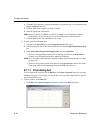
To display the
Advanced Pin Mapping dialog box:
1. Click on the
Map Pins button in either the Footprint tab of the Component Properties dialog
box, step 5 of the
Component Wizard, or the Edit Footprint dialog box.