


Adding Components with the Component Wizard
Multicap 9 User Guide 8-7
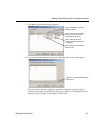
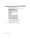
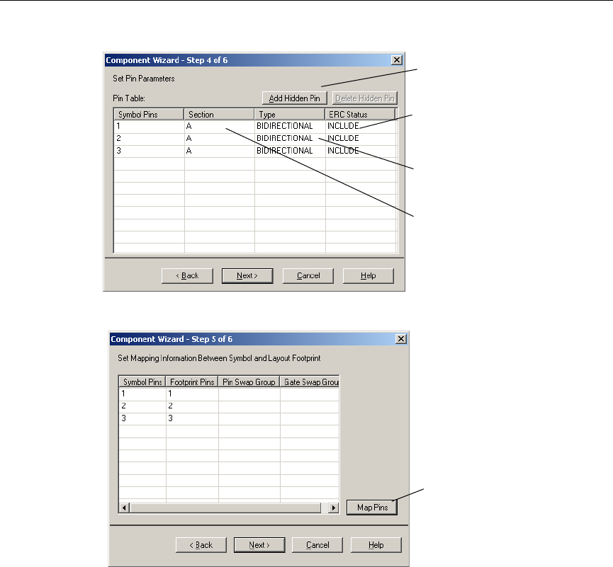
7. Click
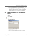
Next. The following dialog box appears.
8. To accept the symbol information displayed, click
Next. Step 5 of the wizard appears.
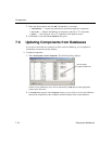
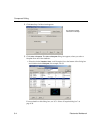
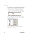
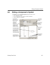
The symbol and footprint pin mapping is needed for exporting to a layout package. A
symbol pin is the name of the pin in the symbol, for example, Vcc. The footprint pin is the
number or name of that pin on the footprint in PCB layout.
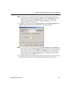
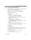
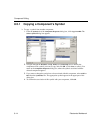
Click in field and select desired
Section for pin.
Click in field and select pin
model type from drop-down list
that appears.
Click in field and select whether
to include or exclude pin from
Electrical Rules Checking.
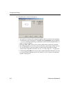
Click to add hidden pins: Power;
Ground; Common.
Displays Advanced Pin Mapping
dialog box