


Schematic Capture - Advanced Functions
5-10 Electronics Workbench
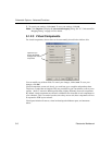
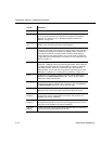
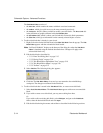
Description The component’s description.
Label The component’s user-defined label. Click on the field and type in desired
text. Can also be entered in the Label tab in the component’s properties
dialog box. For details, see “4.9.1 Modifying Component Labels and
Attributes” on page 4-34.
Coordinate
X/Y
The position of the component on the workspace. This field is read-only and
changes as the component is moved on the workspace.
Rotation Click to display a drop-down list of the selections available to rotate the
component. “Unrotated” is the component’s original position. Other selections
are: Rotated 90 (90 degrees clockwise from original position), Rotated 180
(180 degrees clockwise from original position), Rotated -90 (90 degrees
counter-clockwise from original position). You can also rotate a component
by right-clicking on it in the workspace. For details, see “3.3 Using the Pop-up
Menus” on page 3-10.
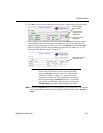
Flip Click to display a drop-down list of the selections available to flip the
component. “Unflipped” is the component’s original position. Other selections
are: Flipped X (horizontal flip from original position), Flipped Y (vertical flip
from original position), Flipped XY (a horizontal and a vertical flip from
original position). You can also flip a component by right-clicking on it in the
workspace. For details, see “3.3 Using the Pop-up Menus” on page 3-10.
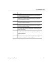
Color Component’s color. “Default” is based on the color scheme selected in the
Circuit tab of the Sheet Properties dialog box. Click to display a Color
palette and select the desired color.
Spacing Minimum distance between the component and another component when
using the shove option in Ultiboard. Unit of measure is set in the PCB tab of
the Sheet Properties dialog box. Click to enter new data.
Group Click in this field to enter a group for a component. This group can be used in
Ultiboard to keep components together during the PCB layout process.
Pin
Swapping
If enabled, allows pins for like-components to be swapped during the PCB
layout process. Click to toggle between Yes and No. This feature is not
available in all versions of Multicap.
Gate
Swapping
If enabled, allows gates with same functionality, such as two NAND gates to
be swapped during PCB layout process. Click to toggle between Yes and No.
This feature is not available in all versions of Multicap.
Lock PCB
Settings
If enabled, prevents changes to parameters that effect layout of components
on the PCB. Click to toggle between Yes and No.
Column Description