


Schematic Capture - Advanced Functions
5-32 Electronics Workbench
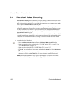
5.4 Electrical Rules Checking
Electrical Rules Checking creates and displays a report detailing connection errors (such as an
output pin connected to a power pin) and unconnected pins.
Once you have wired your circuit, you can check the connections for correctness based on the
rules set up in the
Electrical Rules Check dialog box.
Depending on your circuit, you may wish to have warnings issued if some types of
connections are present, error messages for other connection types, and no warnings or errors
for other connections. You control the type of connections that are reported when Electrical
Rules Checking is done by setting up the rules in the grid found in the
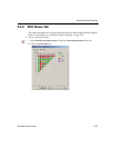
ERC Rules tab of the
Electrical Rules Check dialog box.
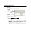
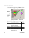
ERC may be run over an entire design, or only across certain areas of a design. When an ERC
is run, any anomalies are reported into a results pane at the bottom of the screen and the circuit
is annotated with circular error markers. Clicking on an error will center and zoom on the
error location.
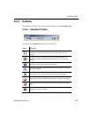
To run the electrical rules check:
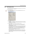
1. Select
Tools/Electrical Rules Check to display the Electrical Rules Check dialog box.
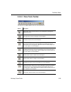
2. Set up the reporting options as described in “5.4.1 ERC Options Tab” on page 5-35 and
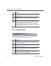
“5.4.2 ERC Rules Tab” on page 5-37.
3. Set up the rules as described in “5.4.2 ERC Rules Tab” on page 5-37.
4. Click
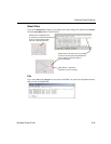
OK. The results display in the format selected in the Output box in the ERC Options
tab.
In the following examples, a power pin has been connected to an output pin, which was
defined as an error in the
ERC Rules tab. All others pins have been left unconnected.
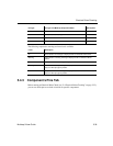
Note You can select whether or not to include specific pins in a component in the ERC.
Refer to “5.4.3 Component’s Pins Tab” on page 5-39 for details.