


Wiring Components
Multicap 9 User Guide 4-19
corresponds to analog ground. GND is a digital ground (as it is common for the purposes of
PCB layout to wish to isolate these two ground nets).
These reserved nets are most often used in conjunction with hidden symbol pins. These are
pins that are not shown on a schematic, as they and their accompanying wires would clutter
the schematic to too great an extent, but are nonetheless connected for the purposes of
simulation and layout. For example, a TTL digital AND gate would implicitly be connected to
GND and VCC via hidden pins.
4.5.1 Wiring Components Automatically
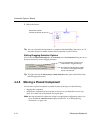
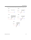
To wire two components together automatically:
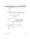
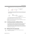
1. Click on a pin from the first component to start the connection (your pointer turns into a
crosshair ) and move the mouse. A wire appears, attached to your cursor.
2. Click on a pin on the second component to finish the connection. Multicap automatically
places the wire, which snaps to an appropriate configuration (unless you have disabled the
“autowire on connection” option, as described in “4.5.6 Setting Wiring Preferences” on
page 4-26). The wire is numbered as a net. After a wire is connected between two pins the
cursor returns to its normal mode and is ready for your next command.
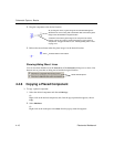
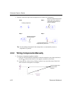
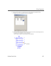
Tip If the connection was not successful, you may be trying to place the wire too close to
other surrounding components. Try to make the connection at a slightly different
location, or use manual wiring, as described in the following section.
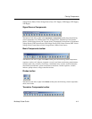
System-generated net number