


Embraer Prodigy
®
Flight Deck 100 Pilot’s Guide
190-00728-04 Rev. A100
ENGINE & AIRFRAME SYSTEMS
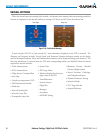
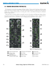
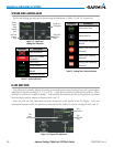
3.1 ENGINE INDICATION SYSTEM (EIS)
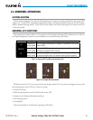
EIS information is presented using gauges and digital readouts. During normal operating conditions, gauge
pointers and readout text appear in green. When unsafe operating conditions occur, gauge pointers and readouts
change color to indicate caution (yellow) or warning (red). Refer to each indicator description for additional
details on display behavior.
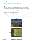
If the time limit for an unsafe condition is exceeded, the color of the pointers and digits may change to denote
an increase in priority level. Parameters out of the range of the readout display as a red “X”. If sensor data for a
parameter becomes invalid or unavailable, a red “X” is displayed across the indicator and/or readout.
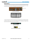
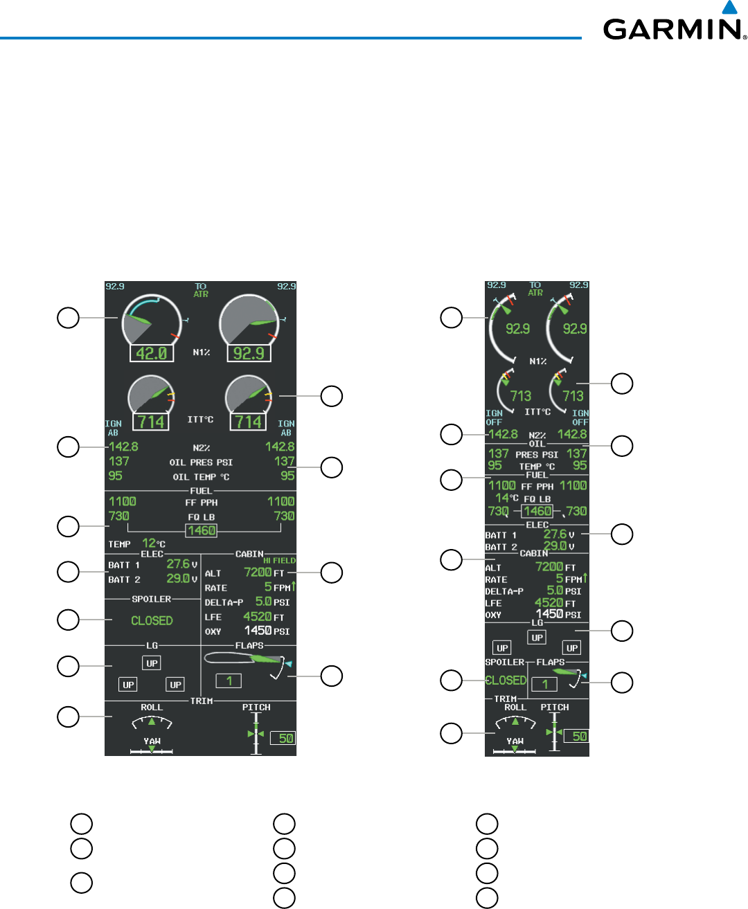
Figure 3-4 EICAS Display (Normal)
11
9
8
7
10
6
5
4
3
2
1
11
8
9
10
7
6
5
4
3
2
1
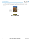
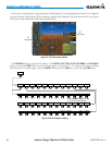
Figure 3-5 EIS Display (Reversionary)
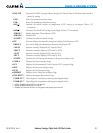
1
Engine Fan Rotation Speed
2
Interstage Turbine
Temperature (ITT)
3
Engine High Pressure
Compressor Rotation Speed
4
Oil Pressure and Temperature
5
Fuel Display
6
Battery Voltmeter
7
Cabin Display
8
Spoiler Status
9
Landing Gear Status
10
Flap Indicator
11
Trim Indicator