


190-00728-04 Rev. A
Embraer Prodigy
®
Flight Deck 100 Pilot’s Guide
171
FLIGHT MANAGEMENT
SECTION 5 FLIGHT MANAGEMENT
5.1 INTRODUCTION
The Prodigy
®
Flight Deck 100 is an integrated flight, engine, communication, navigation and surveillance
system. This section of the Pilot’s Guide explains flight management using the Prodigy
®
Flight Deck 100.
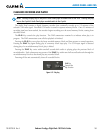
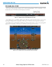
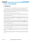
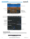
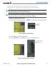
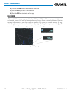
The most prominent part of the system are the three full color displays: two Primary Flight Displays (PFD) and
a Multi Function Display (MFD). The information to successfully navigate the aircraft using the GPS sensors is
displayed on the PFD and the MFD. See examples in the Figure 5-1 and Figure 5-2. Detailed descriptions of flight
management functions are discussed later in this section.
A brief description of the GPS navigation data on the PFD and MFD follows.
Navigation mode indicates which sensor is providing the course data (e.g., GPS, VOR) and the flight plan phase
(e.g., Departure (DPRT), Terminal (TERM), Enroute (ENR), Oceanic (OCN), Approach (LNAV, LNAV+V, L/VNAV,
or LPV), or Missed Approach (MAPR)).
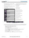
The Inset Map is a small version of the MFD Navigation Map and can be displayed in the lower left corner of
the PFD. When the system is in reversionary mode, the Inset Map is displayed in the lower right corner. The
Inset Map is displayed by pressing the INSET Softkey. Pressing the INSET Softkey again, then pressing the OFF
Softkey removes the Inset Map.
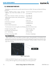
The Navigation Map displays aviation data (e.g., airports, VORs, airways, airspaces), geographic data (e.g.,
cities, lakes, highways, borders), topographic data (map shading indicating elevation), and hazard data (e.g.,
traffic, terrain, weather). The amount of displayed data can be reduced by selecting the DCLTR Softkey. The
Navigation Map can be oriented four different ways: North Up (NORTH UP), Track Up (TRK UP), Desired Track
Up (DTK UP), or Heading Up (HDG UP).
An aircraft icon is placed on the Navigation Map at the location corresponding to the calculated present position.
The aircraft position and the flight plan legs are accurately based on GPS calculations. The basemap upon which
these are placed are from a source with less resolution, therefore the relative position of the aircraft to map features
is not exact. The leg of the active flight plan currently being flown is shown as a magenta line on the navigation
map. The other legs are shown in white.
There are 28 different map ranges available, from 500 feet to 2000 nm. The current range is indicated in the
lower right corner of the map and represents the top-to-bottom distance covered by the map. To change the map
range on any map, turn the Joystick counter-clockwise to zoom in ( -, decreasing), or clockwise to zoom out (+,
increasing).
The Direct-to Window, the Flight Plan Window, the Procedures Window, and the Nearest Airports Window
can be displayed in the lower right corner of the PFD. Details of these windows are discussed in detail later in
the section.