


190-00728-04 Rev. A
Embraer Prodigy
®
Flight Deck 100 Pilot’s Guide
27
SYSTEM OVERVIEW
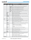
1.6 SYSTEM OPERATION
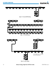
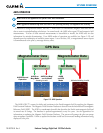
The displays are connected via a single Ethernet bus, thus allowing for high-speed communication. As shown
in Figure 1-1. The GIA 63W #1 is connected to PFD1 and GIA 63W #2 is connected to the HSDB switch. This
section discusses the normal and reversionary modes of operation as well as the various AHRS modes of the
system.
In the event of display failure, the display modes are as follows:
•
PFD1 failure
– MFD enters reversionary mode; PFD2 remains in normal mode.
•
MFD failure
– PFD1 and PFD2 enter reversionary mode.
•
PFD2 failure
– PFD1 and the MFD remain in normal mode.
NORMAL OPERATION
PFD
In normal mode, the PFD presents graphical flight instrumentation (attitude, heading, airspeed, altitude
and vertical speed), thereby replacing the traditional flight instrument cluster. The PFD also offers control for
COM and NAV frequency selection.
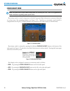
MFD
In normal mode, the right portion of the MFD displays a full-color moving map with navigation information,
while the left portion of the MFD is dedicated to engine, fuel, electrical, cabin pressurization, oxygen, landing
gear, and trim/flaps indication.
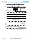
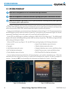
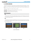
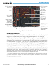
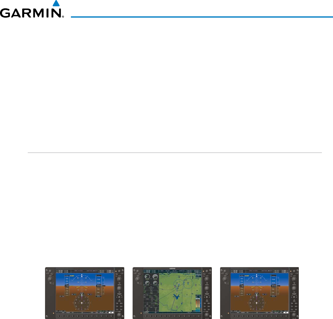
Figure 1-20 gives an example of the system displays in normal mode.
Figure 1-20 Normal Operation
MFD PFD1 PFD2