


Embraer Prodigy
®
Flight Deck 100 Pilot’s Guide
190-00728-04 Rev. A
362
HAZARD AVOIDANCE
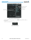
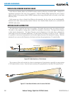
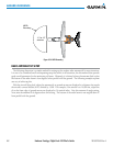
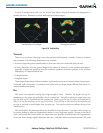
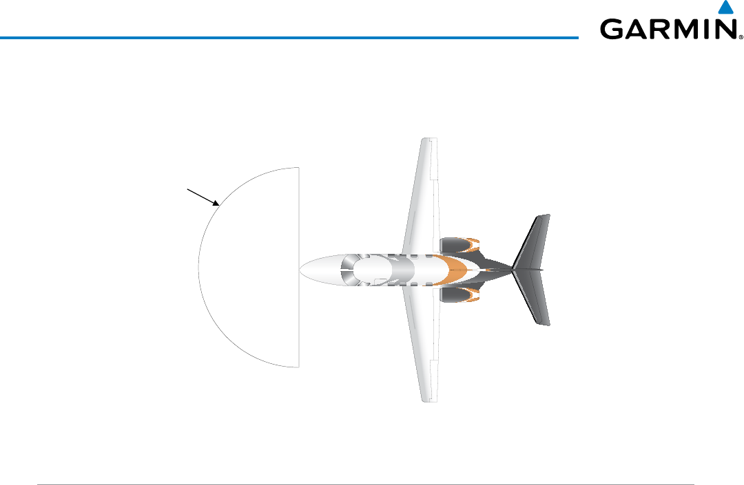
11’ for 12”
antenna
MPEL
Boundary
Figure 6-54 MPEL Boundary
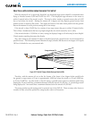
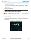
BASIC ANTENNA TILT SETUP
Thefollowingdiscussionisasimplemethodforsettinguptheweatherradarantennatiltformostsituations.
Itisnottobeconsideredanallencompassingsetupthatworksinallsituations,butthismethoddoesprovide
good overall parameters for the monitoring of threats. Ultimately, it is desired to have the antenna tilted so that
thebottomoftheradarbeamisfourdegreesbelowparallelwiththeground.Thefollowingexampleexplains
one way of achieving this.
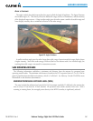
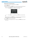
Withtheaircraftyinglevel,adjusttheantennatiltsogroundreturnsaredisplayedatadistancethatequals
theaircraft’scurrentaltitude(AGL)dividedby1,000.Forexample,iftheaircraftisat14,000feet,adjustthe
tiltsothefrontedgeofgroundreturnsaredisplayedat14nauticalmiles.Notethisantennatiltanglesetting.
Now,raisetheantennatilt6degreesabovethissetting.Thebottomoftheradarbeamisnowangleddown4º
from parallel with the ground.