


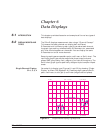
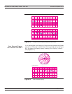
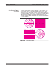
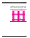
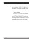
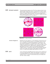

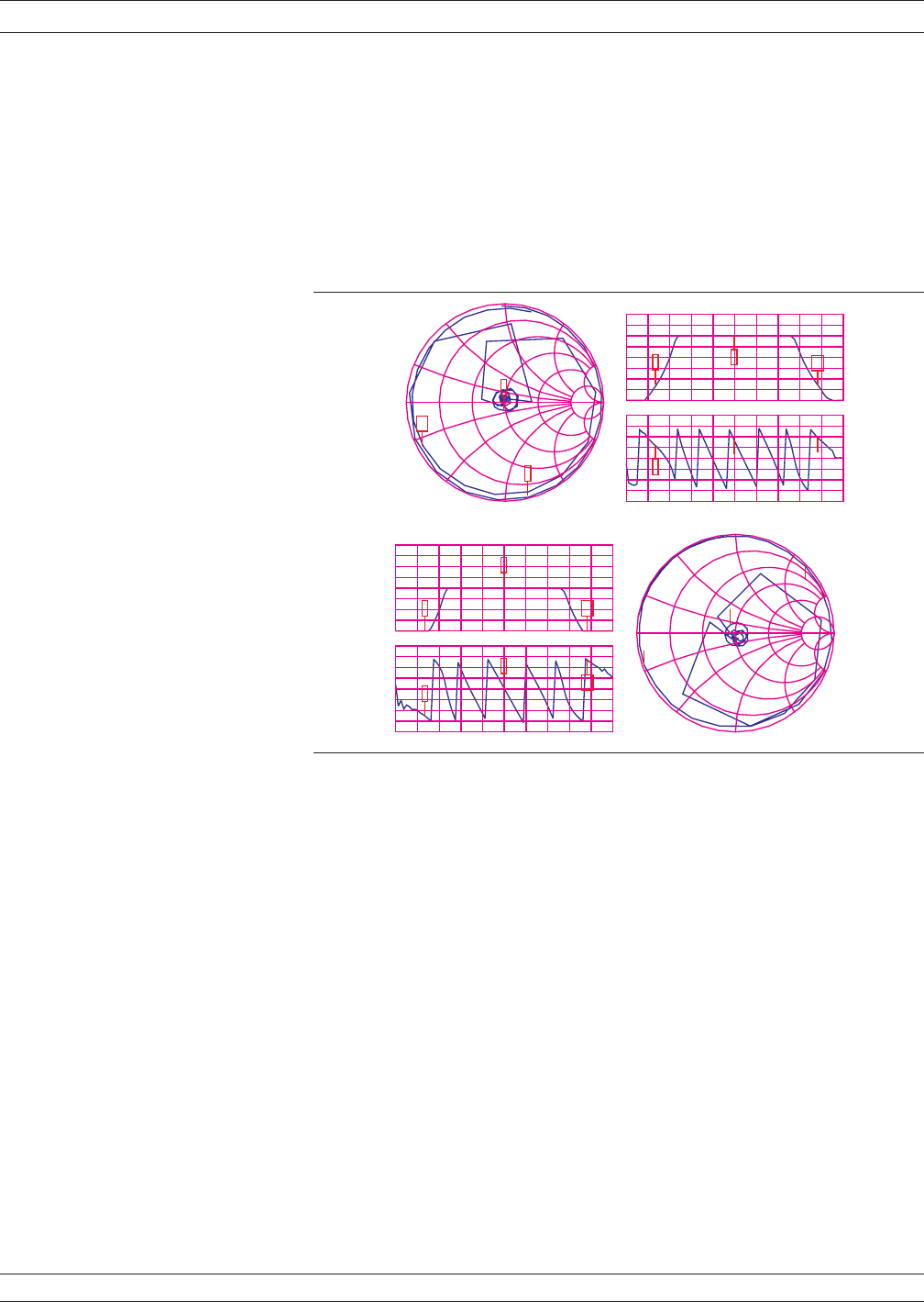
6-3 FREQUENCY MARKERS The example below shows how the 37xxxE annotates markers for the
different graph-types. Each marker is identified with its own number.
When a marker reaches the top of its graticule, it will flip over and its
number will appear below the symbol. When markers approach the
same frequency, they will overlap. Their number will appear as close to
the marker as possible without overlapping.
Marker Designation
Depending on menu selection, you may designate a marker as the “ac
-
tive” or the “delta reference” marker. If you choose a marker to be ac
-
tive—indicated by its number being enclosed in a square box—you
may change its frequency or time (distance) (or point number in CW
Draw) with the Data Entry keypad or knob. If you have chosen it to be
the delta-reference marker, a delta symbol (D) appears one character
space above the marker number (or one character space below a
“flipped” marker). If the marker is both active and the delta reference
marker, the number and the delta symbol appear above (below) the
marker. The delta symbol appears above (below) the number.
6-4 LIMITS Limit lines function as settable maximum and minimum indicators for
the value of displayed data. These lines are settable in the basic units
of the measurement on a channel-by-channel basis. If the display is
rescaled, the limit line(s) will move automatically and thereby main
-
tain their correct value(s).
37xxxE OM 6-11
DATA DISPLAYS FREQUENCY MARKERS
0
.2
-.2
.5
-.5
1
-1
2
-2
5
-5
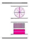
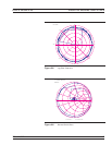
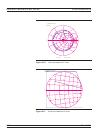
S11
Z
GHz2.036000000 10.020000000
S12 LOGM+P
-20.000 dB
3.91|
10.000 dB/DIV
60.00| /DIV
GHz2.036000000 10.020000000
S21 LOGM+P
0.000 dB
7.99|
10.000 dB/DIV
60.00| /DIV
0
.2
-.2
.5
-.5
1
-1
2
-2
5
-5
S22
Z
1
2
3
1
2
3
1
2
3
1
2
3
1
2
3
1
2
3
Figure 6-12. Marker Annotation